Pomera DM250 Tinkering
The KING JIM Pomera DM250 "digital typewriter" is a small Linux-powered ARM computer that boots up into a custom word processor application. I've been tinkering with it to try to get OpenBSD booted on it. I'd normally wait until the end and write up a proper article explaining everything, but this process is taking a lot longer than I expected so I figured I'd document it all as I go.
Background
KING JIM has made a number of portable word processors starting with the DM5, the DM10 and DM20 with fold-out keyboards, then the DM100 and DM200 which share the form factor with its latest DM250.
I only know of KING JIM because stsp@ has their Portabook x86 machine that has required a handful of tweaks to get OpenBSD working on it.
The DM250 was only sold in Japan, but the manufacturer recently launched an Indiegogo campaign to launch a US version ("DM250US") with an ANSI keyboard layout and defaulting to English in the software (the Japanese model has English support in its software and can use the keyboard in English, though with its slightly different layout). I learned about this on the writerDeck subreddit which I subscribe to for some reason.
The unit measures 10.35" wide by 4.72" tall, with a height of 0.7" when closed. It has a 7" 1024x600 full-color TFT LCD screen, though the DM250's custom word processing software only uses black and white. It weighs 1.4 lbs and has a soft-touch rubber coating on its case. Its DM250US now has a US layout, though the arrow keys were unfortunately moved from an inverted "T" layout on the Japanese DM250 to a horizontal layout.
The DM250 is powered by a Rockchip RK3128 quad-core ARM Cortex-A7 processor with 1GB of RAM and about 8GB of eMMC storage. It has a full-size SD card slot and USB-C for charging. It has an AMPAK AP6236 Wi-Fi and Bluetooth SDIO chip which is based on the Broadcom BCM43436.
2025-03-14
I backed the Indiegogo campaign on February 19th and used Buyee to buy a Japanese model DM250 while I waited for the US campaign to end and for mine to ship out. The Japanese DM250 arrived on the 13th and with the aid of this website, I was able to boot into a Debian build and start inspecting how the device worked. I also took backups of the eMMC flash to be able to recover to it if I screw things up.
I haven't really been interested in the random armv7 boards that run OpenBSD because they all seemed to be similar while also each having quirks that make them unusable for daily use due to lacking driver support or cheap hardware. The DM250 appealed to me because it was a complete computer with keyboard and screen, not just a lone board with an ethernet port. (Although I'm sure I will eventually come up short on complete driver support on this machine too.)
It can turn on "instantly" due to some proprietary software called "LINEOWarp" which integrates into u-boot and the Linux kernel and basically hibernates the machine after booting and writes out its RAM to the eMMC. Upon opening the lid, u-boot directly reads the WARP image and loads it into RAM, bypassing the Linux kernel boot process. I first heard about this type of software from dosdude1's Honda infotainment video which has a similar need for "instant on".
2025-03-19
Trying to get OpenBSD loaded will require updating u-boot on the DM250 to a newer release with EFI support. EFI support was added in 2015 but the DM250 has a build from 2014.
But I can't really mess with u-boot until I get access to the UART on the device and I haven't been able to find the UART pins. I tried booting to Linux and printing random garbage to the serial port while I probed every pin on the board with my Saleae looking for serial data. For some reason nothing came out anywhere.
Eventually I found this page which shows where the UART pins are, which I definitely probed and found nothing while Debian was running. But once I kept leads on those pins while powering on, I could see u-boot output. Now I can actually see what's going on.
U-Boot 2014.10-RK3128-06 (Mar 17 2022 - 14:28:55)

CPU: rk3128
CPU's clock information:
	arm pll = 816000000HZ
	periph pll = 594000000HZ
	ddr pll = 600000000HZ
	codec pll = 400000000HZ
Board:  Rockchip platform Board
Uboot as second level loader
DRAM:  Found dram banks:1
Adding bank:0000000060000000(0000000040000000)
512 MiB
[...]
I'm not sure why u-boot shows 512 MB of RAM there when the DM250 has 1 GB,
especially when that bank output shows a size of 0x40000000 (1,073,741,824
bytes).
2025-03-31
While trying to solder wires to the UART pins, I damaged one of the pads :/ The device still works otherwise so I'll just sell this one and wait for my US model to arrive.
I learned that Rockchip SoCs have a neat feature where if the firmware fails
to load a bootloader from eMMC or SDMMC, it will automatically launch into a
"MaskROM" mode
where it becomes a ugen device over its USB-C cable and allows the attached
computer to directly read and write data to the eMMC.
This way the device can never really be bricked which makes me more confident
testing u-boot changes.
This MaskROM mode works even before SDRAM is initialized, so the first thing
that has to be done is sending it a RAM training blob, then a more complete
usbplug blob which allows more complicated commands over USB.
This can be done with
rkflashtool
or
xrock
which both work on OpenBSD.
$ doas xrock maskrom rk3128_ddr_300MHz_v2.12.bin rk3128_usbplug_v2.63.bin
After uploading the blobs, the device detaches and reattaches into its USB loader mode:
ugen0 at uhub3 port 3 "vendor 0x2207 product 0x310c" rev 2.00/1.00 addr 9
ugen0 detached
ugen0 at uhub3 port 3 "RockChip USB-MSC" rev 2.00/1.00 addr 9
If the flashed u-boot does boot but it's broken, one can short the eMMC to
ground while the board is being powered on and force it into MaskROM mode.
On the DM250, this can be done by shorting TP501 to ground.
2025-04-02
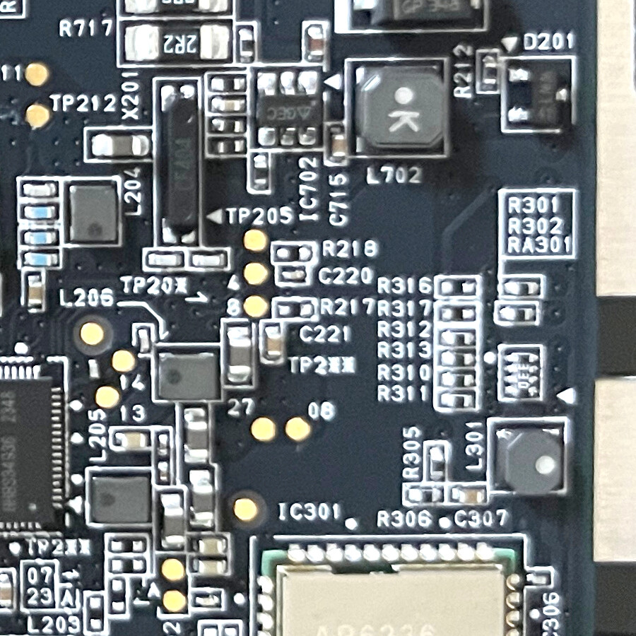
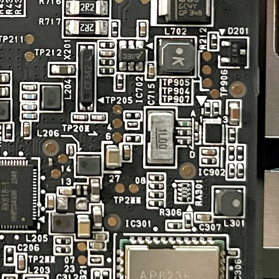
My DM250US arrived. A quick teardown shows it's basically the same hardware but with a different version silkscreened.
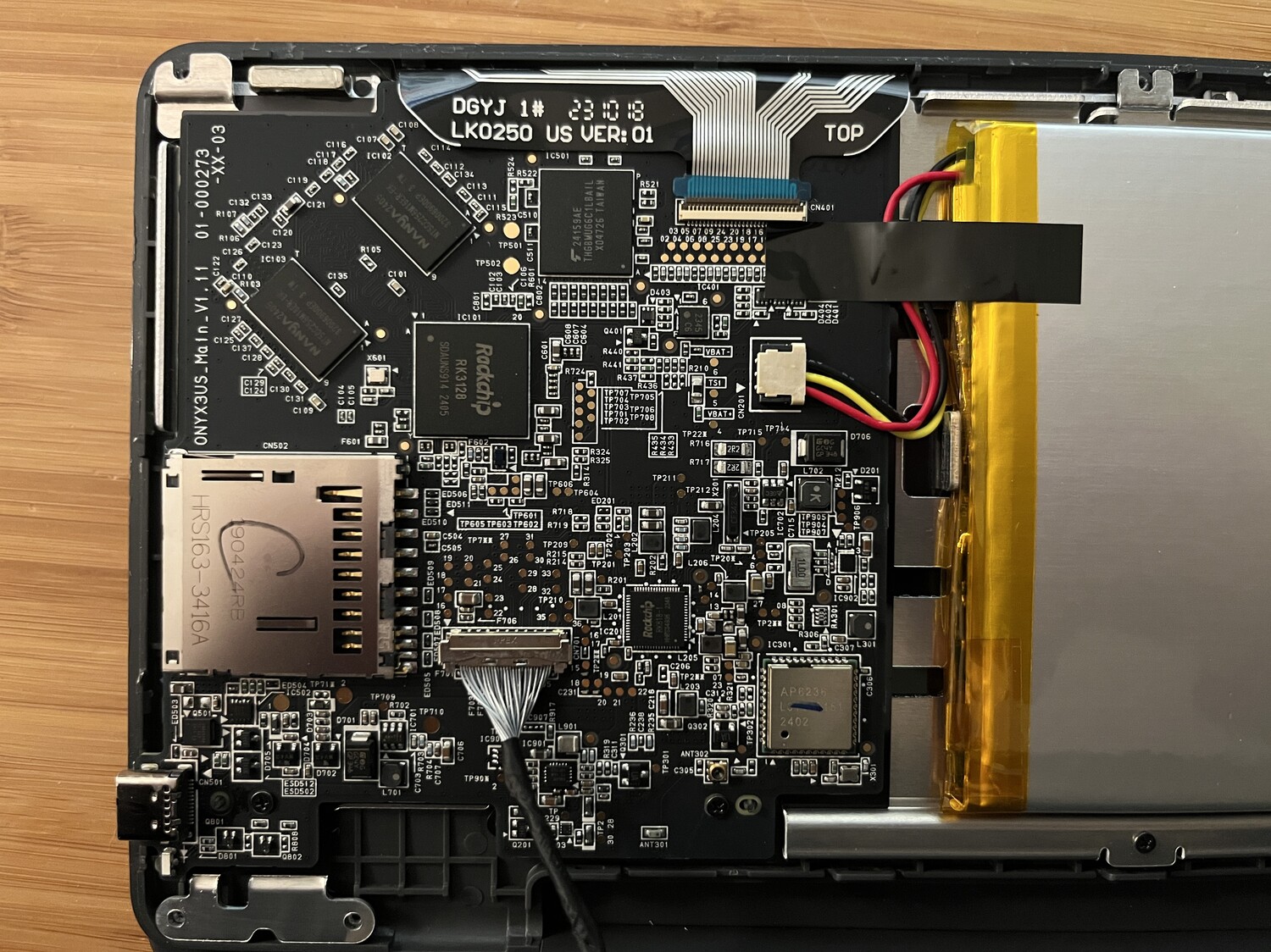
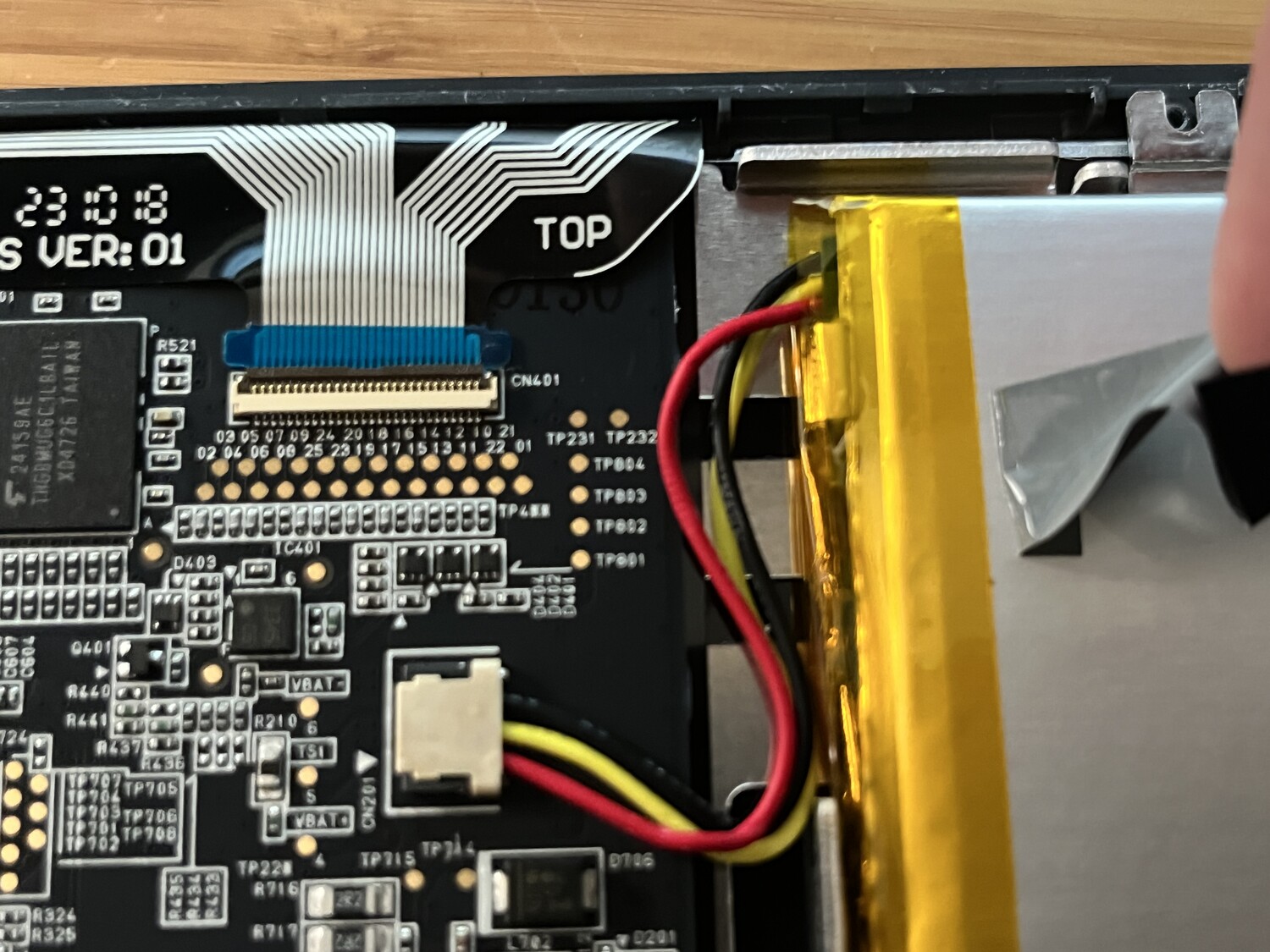
The keyboard keys feel slightly smaller in size and rougher in texture. u-boot appears to be the same version but the build date is newer:
U-Boot 2014.10-RK3128-06 (Oct 07 2024 - 17:22:56)
The kernel is still Linux 3.10.0 with WARP patches. The DTB stored on the eMMC is mostly the same but with these additions:
bq27z558-battery@55 {
	compatible = "ti,bq27z561";
	reg = <0x55>;
	gpios = <0x76 0x12 0x01 0x75 0x0d 0x01>;
	status = "okay";
};

bq256xx-charger@6b {
	compatible = "ti,bq25620";
	reg = <0x6b>;
	gpios = <0x76 0x11 0x01>;
	ti,watchdog-timeout-ms = <0x00>;
	charge-current-limit-microamp = <0x2bf200>;
	charge-voltage-limit-microvolt = <0x408b70>;
	input-current-limit-microamp = <0x2dc6c0>;
	minimal-system-voltage-microvolt = "\0.c";
	pre-charge-control-microamp = <0x8d9a0>;
	termination-control-microamp = <0x249f0>;
	ti,no-thermistor = <0x01>;
	status = "okay";
};
2025-04-03
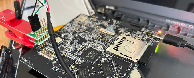
I got this pogo-pin clip from Adafruit to access the UART pins without having to solder to them and potentially damage them again. It's definitely made it much easier to reliably access the UART across multiple reboots.
2025-04-14
I've been trying to get different u-boot trees compiling and booting but none
were working except the
one from KING JIM.
I tried
rockchip-linux/u-boot
and
linux-rockchip/u-boot-rockchip
but neither boot (or at least don't output anything to uart1.
Geniatech
make the
XPI-3128
which is basically the
rk3128-evb
evaluation board that exists in u-boot.
While digging around their
documentation,
I found
this huge tarball
that includes a snapshot of their u-boot tree which is based on newer 2017.09
and has most of the necessary Rockchip drivers.
I'm not sure why Rockchip is so special that they can't do everything in the
official upstream u-boot tree…
With a few changes to build with a newer gcc, setting CONFIG_DEBUG_UART_BASE
to 0x20064000 (uart1 instead of uart2), adding some
custom uart initialization
code
to arch/arm/mach-rockchip/rk3128/rk3128.c, and adding an rk3128-specific
timer driver, I now have a working build of u-boot that has EFI support!
U-Boot 2017.09-g5d36672-dirty (Apr 12 2025 - 12:31:04 -0500)

Model: KING JIM Pomera DM250US
DRAM:  512 MiB
Sysmem: init
Relocation Offset: 00000000, fdt: 00000000
Using default environment

dwmmc@10214000: 1, dwmmc@1021c000: 0
mmc_init: err -110, timer:41969
switch to partitions #0, OK
mmc0(part 0) is current device
Bootdev: mmc 0
MMC0: High Speed, 52Mhz
PartType: RKPARM
rockchip_get_boot_mode: Could not found misc partition
boot mode: normal
Found DTB in resource part
DTB: rk-kernel.dtb
CLK: (uboot. arm: enter 600000 KHz, init 600000 KHz, kernel 0N/A)
  apll 600000 KHz
  dpll 600000 KHz
  cpll 400000 KHz
  gpll 594000 KHz
  armclk 600000 KHz
  aclk_cpu 148500 KHz
  hclk_cpu 74250 KHz
  pclk_cpu 74250 KHz
  aclk_peri 148500 KHz
  hclk_peri 74250 KHz
  pclk_peri 74250 KHz
=> mmcinfo
Device: dwmmc@1021c000
Manufacturer ID: 11
OEM: 100
Name: 008GB
Timing Interface: High Speed
Tran Speed: 52000000
Rd Block Len: 512
MMC version 5.1
High Capacity: Yes
Capacity: 7.3 GiB
Bus Width: 8-bit
Erase Group Size: 512 KiB
HC WP Group Size: 4 MiB
User Capacity: 7.3 GiB WRREL
Boot Capacity: 4 MiB ENH
RPMB Capacity: 4 MiB ENH
=> bootefi
bootefi - Boots an EFI payload from memory

Usage:
bootefi <image address> [fdt address]
  - boot EFI payload stored at address <image address>.
	If specified, the device tree located at <fdt address> gets
	exposed as EFI configuration table.
Unfortunately only the eMMC (dwmmc@1021c000) is working but the probe of the
SDMMC device at dwmmc@10214000 times out.
This means I can't see an inserted SD card and begin to boot OpenBSD's EFI
loader.
I think this has to do with the device not being powered up at boot. I'm still trying to figure out what is required for this to work since it works in other older Rockchip-specific u-boot trees.
2025-04-14 (Evening)
Success!
U-Boot 2017.09-gcc6b241-dirty (Apr 14 2025 - 17:20:37 -0500)

Model: KING JIM Pomera DM250US
DRAM:  512 MiB
Sysmem: init
Relocation Offset: 00000000, fdt: 00000000
Using default environment

dwmmc@10214000: 1, dwmmc@1021c000: 0
RKPARM: Invalid parameter part table
switch to partitions #0, OK
mmc1 is current device
switch to partitions #0, OK
mmc0(part 0) is current device
Bootdev: mmc 0
MMC0: High Speed, 52Mhz
PartType: RKPARM
rockchip_get_boot_mode: Could not found misc partition
boot mode: normal
Found DTB in resource part
DTB: rk-kernel.dtb
In:    serial
Out:   serial
Err:   serial
CLK: (uboot. arm: enter 600000 KHz, init 600000 KHz, kernel 0N/A)
apll 600000 KHz
dpll 600000 KHz
cpll 400000 KHz
gpll 594000 KHz
armclk 600000 KHz
aclk_cpu 148500 KHz
hclk_cpu 74250 KHz
pclk_cpu 74250 KHz
aclk_peri 148500 KHz
hclk_peri 74250 KHz
pclk_peri 74250 KHz
=> setenv fdtfile rk3128-pomera-dm250us.dtb
=> load mmc 1 ${kernel_addr_r} efi/boot/bootarm.efi
reading efi/boot/bootarm.efi
119296 bytes read in 51 ms (2.2 MiB/s)
=> bootefi ${kernel_addr_r} ${fdt_addr_r}
## Starting EFI application at 62008000 ...
FtlInit fffffffe
Scanning disk nandc@10500000.blk...
rkparm_init_param_from_storage param read fail
RKPARM: Invalid parameter part table
Scanning disk dwmmc@10214000.blk...
Scanning disk dwmmc@1021c000.blk...
Scanning disk rksdmmc@1021c000.blk...
rkparm_init_param_from_storage param read fail
RKPARM: Invalid parameter part table
Scanning disk rksdmmc@10214000.blk...
rkparm_init_param_from_storage param read fail
RKPARM: Invalid parameter part table
Scanning disk rksdmmc@10218000.blk...
rkparm_init_param_from_storage param read fail
RKPARM: Invalid parameter part table
Found 6 disks
Adding bank: 0x60000000 - 0x80000000 (size: 0x20000000)
disks: sd0* sd1 sd2 sd3 sd4 sd5 sd6 sd7 sd8 sd9 sd10 sd11 sd12 sd13 sd14 sd15 sd16 sd17 sd18 sd19 sd20 sd21 sd22 sd23 sd24 sd25 sd26 sd27 sd28 sd29 sd30
>> OpenBSD/armv7 BOOTARM 1.23
boot>
cannot open sd0a:/etc/random.seed: No such file or directory
booting sd0a:/bsd: 2411324+767888+11506208+484492 [188357+107+388448+214048]=0x0
I added some debug printfs to the working u-boot tree and saw that it was
calling
rk_iomux_config(RK_UART2_IOMUX)
when initializing the storage.
That ends up calling
rk_uart_iomux_config()
which does some magic writes to the IOMUX.
Reading the
GRF documentation
and other pieces of code, I learned that GPIO1B needs pins 12 and 14 enabled to
activate mmc0_pwren and mmc0_cmd, and GPIO1C needs pins 0, 2, 4, 6, 8, and
10 enabled to change them from JTAG and UART2 pins to those needed for eMMC.
With that, the SD card is recognized and u-boot can read files from it with its
built-in FAT filesystem support.
The existing config on the eMMC splits up the single drive into many different
partitions like kernel, warp, ro_data, etc., which each show up as
separate disks to the EFI loader.
The EFI loader is read from the SD card and loaded into memory with load mmc 1
${kernel_addr_r} efi/boot/bootarm.efi, and then executed with bootefi
${kernel_addr_r} ${fdt_addr_r}.
OpenBSD's BOOTARM.EFI loads successfully and can list files on the SD card and
start reading and booting bsd.rd.
Unfortunately it goes off into lala land there so I'm not sure what it's doing,
but at least now I can move on to the OpenBSD part of this bringup.
2025-04-17
I've pushed my U-Boot tree to GitHub as it seems to be in a good state now. I split up my changes specific to the rk3128 and then added a specific board config for the DM250. Eventually this will need some work to enable the LVDS LCD at boot time like it was with the factory U-Boot.
I added a uart_putc helper to OpenBSD's armv7 locore0.S to print numbers to
the serial port, and then added them along the boot path to see how far it got.
	.globl  uart_putc               /* send r1 to uart */
uart_putc:
	ldr     r0, =0x20064000
	str     r1, [r0]
	ldr     r2, =0x20064000 + 0x7c  /* UART_USR */
check_usr:
	ldr     r3, [r2]
	tst     r3, #(1<<1)             /* UART_TRANSMIT_FIFO_NOT_FULL */
	beq     check_usr
	bx      lr

[...]
start_mmu:
	mov     r1, #'1'
	bl      uart_putc

[...]
	mov     r1, #'2'
	bl      uart_putc

	/* Enable MMU */
	mrc     CP15_SCTLR(r0)
	orr     r0, r0, #CPU_CONTROL_MMU_ENABLE
	mcr     CP15_SCTLR(r0)
	isb

	mov     r1, #'3'
	bl      uart_putc
This showed it was getting to start_mmu but as soon as it wrote the SCTLR
register to enable the MMU, it stopped outputting.
Mark
pointed out
that this was because there was no mapping in the MMU page table to continue
accessing the UART at 0x20064000.
I added an entry for it:
	MMU_INIT(0x20000000, 0x20000000, 1,
		L1_TYPE_S|L1_S_V7_AP(AP_KRW)|L1_S_V7_AF)
But it still wasn't printing '3'.
After a few hours of debugging and reading more docs, I finally realized that my
dumb uart_putc function was clobbering r0 and r1 which were being used
inside of start_mmu so the page table wasn't getting set up right.
By changing it to just a few inline instructions with no FIFO status checking
and using registers that weren't in use, it could enable the MMU properly and
get to '3' and beyond:
	ldr     r4, =0x20064000
	mov     r5, #'3'
	str     r4, [r5]
Eventually with some more tweaks to the DTB passed from U-Boot to the EFI loader
and to the kernel, the kernel could properly print to the chosen stdout-path
and get to copyright.
Since it is able to do this through the normal com_fdt_init_cons routine in
dev/fdt/com_fdt.c which does a bus_space_map, I could remove all of my
debugging from locore0 and then remove my custom UART page table entry.
It can now get to copyright with no kernel changes:
disks: sd0* sd1 sd2
>> OpenBSD/armv7 BOOTARM 1.23
boot> b bsd.arm
cannot open sd0a:/etc/random.seed: No such file or directory
booting sd0a:bsd.arm: 4910236+1012484+138796+608784
[2789902+360416+184+330342]=0x0

OpenBSD/armv7 booting ...
arg0 0xc0caf850 arg1 0x0 arg2 0x9ac83000
Allocating page tables
IRQ stack: p0x60cde000 v0xc0cde000
ABT stack: p0x60cdf000 v0xc0cdf000
UND stack: p0x60ce0000 v0xc0ce0000
SVC stack: p0x60ce1000 v0xc0ce1000
Creating L1 page table at 0x60cb0000
Mapping kernel
Constructing L2 page tables
undefined page type 0x2 pa 0x60000000 va 0x60000000 pages 0x2000 attr 0x8
type 0x7 pa 0x62000000 va 0x60000000 pages 0x6000 attr 0x8
type 0x4 pa 0x68000000 va 0x68000000 pages 0x7 attr 0x8
type 0x7 pa 0x68008000 va 0x60000000 pages 0x32c7b attr 0x8
type 0x2 pa 0x9ac83000 va 0x9ac83000 pages 0x7 attr 0x8
type 0x7 pa 0x9ac8a000 va 0x9ac8a000 pages 0x4 attr 0x8
type 0x7 pa 0x9ac8e000 va 0x9ac8e000 pages 0x2 attr 0x8
type 0x7 pa 0x9ac90000 va 0x9ac90000 pages 0x1 attr 0x8
type 0x2 pa 0x9ac91000 va 0x9ac91000 pages 0x100 attr 0x8
type 0x2 pa 0x9ad91000 va 0x9ad91000 pages 0x1e attr 0x8
type 0x6 pa 0x9adaf000 va 0x9adaf000 pages 0x1 attr 0x8000000000000008
type 0x0 pa 0x9adb0000 va 0x9adb0000 pages 0x1 attr 0x8
type 0x0 pa 0x9adb1000 va 0x9adb1000 pages 0x1 attr 0x8
type 0x0 pa 0x9adb2000 va 0x9adb2000 pages 0x1 attr 0x8
type 0x0 pa 0x9adb3000 va 0x9adb3000 pages 0x1 attr 0x8
type 0x0 pa 0x9adb4000 va 0x9adb4000 pages 0x1 attr 0x8
type 0x0 pa 0x9adb5000 va 0x9adb5000 pages 0x1 attr 0x8
type 0x0 pa 0x9adb6000 va 0x9adb6000 pages 0x1 attr 0x8
type 0x2 pa 0x9adb7000 va 0x9adb7000 pages 0x308c attr 0x8
type 0x5 pa 0x9de43000 va 0x9de43000 pages 0x1 attr 0x8000000000000008
type 0x2 pa 0x9de44000 va 0x9adb7000 pages 0x21bc attr 0x8
pmap [ using 3481620 bytes of bsd ELF symbol table ]
Copyright (c) 1982, 1986, 1989, 1991, 1993
	The Regents of the University of California.  All rights reserved.
Copyright (c) 1995-2025 OpenBSD. All rights reserved.  https://www.OpenBSD.org
Now I just need to figure out how far into init_main.c it's getting and why it
hangs after printing the copyright line.
2025-04-21
With some instrumenting I figured out the kernel was getting as far as setting
up the page tables for the MMU and would then lock up when doing a memset on
the newly setup memory.
By reducing the amount of memory used, I could get it to fully boot the kernel
to !cold, but it crashes in userland:
U-Boot 2017.09-g9333465-dirty (Apr 21 2025 - 13:38:25 -0500)

Model: KING JIM Pomera DM250
DRAM:  1 GiB
Sysmem: init
Relocation Offset: 3ddc2000, fdt: 00000000
Using default environment

Failed to load DTB
Failed to get kernel dtb, ret=-1
In:    serial
Out:   serial
Err:   serial
Model: KING JIM Pomera DM250
dwmmc@10214000: 1, dwmmc@1021c000: 0
switch to partitions #0, OK
mmc1 is current device
switch to partitions #0, OK
mmc0(part 0) is current device
Bootdev: mmc 0
MMC0: High Speed, 52Mhz
## Unknown partition table type 0
PartType: <NULL>
rockchip_get_boot_mode: Could not found misc partition
boot mode: normal
CLK: (uboot. arm: enter 600000 KHz, init 600000 KHz, kernel 0N/A)
  apll 600000 KHz
  dpll 600000 KHz
  cpll 400000 KHz
  gpll 594000 KHz
  armclk 600000 KHz
  aclk_cpu 148500 KHz
  hclk_cpu 74250 KHz
  pclk_cpu 74250 KHz
  aclk_peri 148500 KHz
  hclk_peri 74250 KHz
  pclk_peri 74250 KHz
Hit key to stop autoboot('CTRL+C'):  0
switch to partitions #0, OK
mmc1 is current device
Scanning mmc 1:1...
reading /kingjim-dm250.dtb
23239 bytes read in 6 ms (3.7 MiB/s)
Found EFI removable media binary efi/boot/bootarm.efi
reading efi/boot/bootarm.efi
119564 bytes read in 16 ms (7.1 MiB/s)
## Starting EFI application at 62008000 ...
FtlInit fffffffe
Scanning disk nandc@10500000.blk...
Scanning disk dwmmc@10214000.blk...
Scanning disk dwmmc@1021c000.blk...
Found 3 disks
Adding bank: 0x60000000 - 0xa0000000 (size: 0x40000000)
disks: sd0* sd1 sd2 sd3
>> OpenBSD/armv7 BOOTARM 1.23
boot> b sd0a:/bsd.rd
cannot open sd0a:/etc/random.seed: No such file or directory
booting sd0a:/bsd.rd: 4916868+1014156+16731272+608976
[2791939+360736+184+330515]=0x0

OpenBSD/armv7 booting ...
arg0 0xc1c8514c arg1 0x0 arg2 0x9ac82000
Allocating page tables
IRQ stack: p0x61cb4000 v0xc1cb4000
ABT stack: p0x61cb5000 v0xc1cb5000
UND stack: p0x61cb6000 v0xc1cb6000
SVC stack: p0x61cb7000 v0xc1cb7000
Creating L1 page table at 0x61c88000
Mapping kernel
Constructing L2 page tables
undefined page type 0x2 pa 0x60000000 va 0x60000000 pages 0x2000 attr 0x8
type 0x7 pa 0x62000000 va 0x60000000 pages 0x6000 attr 0x8
initarm: added 24576 pages at 0x62000000, physmem now 32768
type 0x4 pa 0x68000000 va 0x68000000 pages 0x7 attr 0x8
type 0x7 pa 0x68008000 va 0x60000000 pages 0x32c7a attr 0x8
initarm: added 103997 pages at 0x68008000, physmem now 136765
type 0x2 pa 0x9ac82000 va 0x9ac82000 pages 0x7 attr 0x8
type 0x7 pa 0x9ac89000 va 0x9ac89000 pages 0x4 attr 0x8
type 0x7 pa 0x9ac8d000 va 0x9ac8d000 pages 0x2 attr 0x8
type 0x7 pa 0x9ac8f000 va 0x9ac8f000 pages 0x1 attr 0x8
type 0x2 pa 0x9ac90000 va 0x9ac90000 pages 0x100 attr 0x8
type 0x2 pa 0x9ad90000 va 0x9ad90000 pages 0x1e attr 0x8
type 0x6 pa 0x9adae000 va 0x9adae000 pages 0x1 attr 0x8000000000000008
type 0x0 pa 0x9adaf000 va 0x9adaf000 pages 0x1 attr 0x8
type 0x0 pa 0x9adb0000 va 0x9adb0000 pages 0x1 attr 0x8
type 0x0 pa 0x9adb1000 va 0x9adb1000 pages 0x1 attr 0x8
type 0x0 pa 0x9adb2000 va 0x9adb2000 pages 0x1 attr 0x8
type 0x0 pa 0x9adb3000 va 0x9adb3000 pages 0x1 attr 0x8
type 0x0 pa 0x9adb4000 va 0x9adb4000 pages 0x1 attr 0x8
type 0x0 pa 0x9adb5000 va 0x9adb5000 pages 0x1 attr 0x8
type 0x0 pa 0x9adb6000 va 0x9adb6000 pages 0x1 attr 0x8
type 0x2 pa 0x9adb7000 va 0x9adb7000 pages 0x308c attr 0x8
type 0x5 pa 0x9de43000 va 0x9de43000 pages 0x1 attr 0x8000000000000008
type 0x2 pa 0x9de44000 va 0x9adb7000 pages 0x21bc attr 0x8
pmap [ using 3484148 bytes of bsd ELF symbol table ]
Copyright (c) 1982, 1986, 1989, 1991, 1993
	The Regents of the University of California.  All rights reserved.
Copyright (c) 1995-2025 OpenBSD. All rights reserved.  https://www.OpenBSD.org

OpenBSD 7.7 (obj.amd64.armv7) #113: Fri Apr 18 11:15:57 CDT 2025
	jcs@nano.jcs.org:/usr/src/sys/arch/armv7/compile/GENERIC/obj.amd64.armv7
real mem  = 560189440 (534MB)
avail mem = 520486912 (496MB)
random: boothowto does not indicate good seed
mainbus0 at root: KING JIM Pomera DM250
cortex0 at mainbus0
psci0 at mainbus0: PSCI 0.0
syscon0 at mainbus0: can't map registers
syscon1 at mainbus0: "syscon"
ampintc0 at mainbus0 nirq 160, ncpu 4: "interrupt-controller"
syscon2 at mainbus0: "syscon"
agtimer0 at mainbus0: 24000 kHz
agtimer1 at mainbus0: 24000 kHz
com0 at mainbus0: dw16550, 64 byte fifo
com0: probed fifo depth: 0 bytes
com1 at mainbus0: dw16550
com1: console
com2 at mainbus0: dw16550
ehci0 at mainbus0
usb0 at ehci0: USB revision 2.0
uhub0 at usb0 configuration 1 interface 0 "Generic EHCI root hub" rev 2.00/1.00
addr 1
ohci0 at mainbus0: version 1.0
dwmmc0 at mainbus0: 18 MHz base clock
sdmmc0 at dwmmc0: 4-bit, dma
dwmmc1 at mainbus0: 25 MHz base clock
sdmmc1 at dwmmc1: 8-bit, dma
rkiic0 at mainbus0
iic0 at rkiic0
"rockchip,rk818" at iic0 addr 0x1c not configured
rkiic1 at mainbus0
iic1 at rkiic1
pcxrtc0 at iic1 addr 0x51pcxrtc0: pcxrtc_reg_read: failed to read reg0
pcxrtc0: pcxrtc_reg_write: failed to write reg0
pcxrtc0: pcxrtc_reg_read: failed to read reg2
: battery ok
rkiic2 at mainbus0
iic2 at rkiic2
rkiic3 at mainbus0
iic3 at rkiic3
usb1 at ohci0: USB revision 1.0
uhub1 at usb1 configuration 1 interface 0 "Generic OHCI root hub" rev 1.00/1.00
addr 1
scsibus0 at sdmmc0: 2 targets, initiator 0
sd0 at scsibus0 targ 1 lun 0: <Sandisk, SL32G, 0080> removable
sd0: 30436MB, 512 bytes/sector, 62333952 sectors
scsibus1 at sdmmc1: 2 targets, initiator 0
sd1 at scsibus1 targ 1 lun 0: <Toshiba, 008GB1, 0000> removable
sd1: 7456MB, 512 bytes/sector, 15269888 sectors
vscsi0 at root
scsibus2 at vscsi0: 256 targets
softraid0 at root
scsibus3 at softraid0: 256 targets
bootfile: sd0a:/bsd
boot device: sd0
root on rd0a swap on rd0b dump on rd0b
pcxrtc0: pcxrtc_clock_read: failed to read rtc
WARNING: bad clock chip time
WARNING: CHECK AND RESET THE DATE!
Fatal kernel mode prefetch abort at 0x00000000
trapframe: 0xcd06ba70
IFSR=00000005, IFAR=00000000, spsr=80000113
r0 =00000000, r1 =00000007, r2 =c18a0868, r3 =60000113
r4 =00000007, r5 =c93ad000, r6 =c93ad000, r7 =cd06bb10
r8 =cd06a000, r9 =00000013, r10=c08a8988, r11=cd06bb08
r12=c18e5378, ssp=cd06bac0, slr=c0780344, pc =00000000

Stopped at      0

ddb> trace
0
		rlv=0xc032fd30 rfp=0xcd06bb90
exception_exit
		rlv=0xc0343800 rfp=0xcd06bee0
sys_execve+0x2c8 [/usr/src/sys/kern/kern_exec.c:361]
		rlv=0xc04c4450 rfp=0xcd06bfa8
start_init+0x254 [/usr/src/sys/kern/init_main.c:716]
		rlv=0xc07976ac rfp=0xc1cb8f90
Bad frame pointer: 0xc1cb8f90
I'm still not sure why the memory limiting is needed, but apparently U-boot is not passing the proper memory segment information to the EFI bootloader for the kernel to know to avoid that address space.
Since I was able to reduce the custom things needed in U-boot, I tried adapting my UART, GPIO, and timer changes to mainline U-boot to see if maybe the EFI code was better there. It boots now with UART output but the SDMMC and eMMC driver fails to setup either one of them:
U-Boot 2025.01-00001-g4e6a9d7df66d-dirty (Apr 19 2025 - 22:17:13 -0500)

Model: KING JIM Pomera DM250
DRAM:  1 GiB
Core:  30 devices, 14 uclasses, devicetree: embed
MMC:   mmc@10214000: 1, mmc@1021c000: 0
Loading Environment from nowhere... OK
In:    serial@20064000
Out:   serial@20064000
Err:   serial@20064000
Hit any key to stop autoboot:  0
Card did not respond to voltage select! : -110
Cannot persist EFI variables without system partition
Card did not respond to voltage select! : -110
No USB controllers found
I can see the udelay calls work properly (which weren't in the
Rockchip-specific U-boot tree until I made the RK3128-specific timer changes),
and where it's failing to respond to voltage is past the initial setup which
requires responses from the controllers so it seems like they are being powered
up.
2025-04-21 (Evening)
I guess I should have read the kernel panic better.
Fatal kernel mode prefetch abort at 0x00000000 and pc =00000000 indicate
that the kernel set the program counter to 0, which meant it was probably
executing a function callback that was pointing to NULL.
After dozens of printfs added, kernels recompiled, SD cards swapped, and reset
pins grounded, I figured out that the kernel was panicking in
data_abort_handler because curcpu()->ci_flush_bp was NULL and there was no
check for that (because it shouldn't really happen).
Why it was NULL was much more complicated.
ci_flush_bp was never initialized because arm/arm/cpu.c was not attaching to
cpu0, because the reg values for cpu0-cpu3 in the FDT were
0x000-0x003, but
mainbus.c
expects them to be 0xf00-0xf03.
They are 0x000-0x003 even in the latest
U-boot
tree
but 0xf00-0xf03 in
Linux
which I guess is now the authoritative source for device trees?
This is why I dislike the ARM ecosystem…
cpu0 at mainbus0 mpidr f00: ARM Cortex-A7 r0p5
cpu0: 32KB 32b/line 2-way L1 VIPT I-cache, 32KB 64b/line 4-way L1 D-cache
cpu0: 256KB 64b/line 8-way L2 cache
Anyway, now that cpu0 actually attaches and runs cpu_identify, it sets the
CPU device's ci_flush_bp callback to cpu_flush_bp_noop, which does…
nothing.
So the kernel isn't panicking now, but instead it just locks up (actually powers off) when it should be starting userland. I'm getting there…
2025-04-22
Oh, right, we have no
clock
again, so the dwmmc driver's attempt to set the frequency
does nothing
but this isn't handled as an error.
I'll have to add rockchip,rk3128-cru support to the rkclock driver, which
does not look
fun
doing from scratch.
This menial task of translating register definitions from PDFs and cross-referencing Linux driver code is usually where my willpower fades in these types of projects.
2025-04-29
A few weeks ago I bought a Geniatech XPI-3128 which is another board based on the Rockchip 3128, but with 4 USB ports, ethernet, and HDMI. I tried flashing a new U-Boot build to it and it promptly stopped booting. When I'd try powering it on with its recovery button pressed to boot into Maskrom mode, my laptop would just log messages like this:
uhub3: device problem, disabling port 3
So it was as if it was trying to attach but kept failing. The device was basically bricked, so I e-mailed Geniatech's support address for help. A couple weeks later they finally gave me the information I needed, which was that I had to desolder the Wi-Fi board, remove the CPU heatsink, and then the eMMC clock line was reachable to be shorted to ground to avoid loading U-Boot and force Maskrom mode.
That allowed me to flash and test different U-Boot builds again and finally get it booting on the XPI-3128. However, the more I worked on it, the more I realized trying to do anything with my older U-Boot tree was futile.
The device tree (DTB) that shipped on the DM250 (and the XPI-3128) is very old,
and is configured for old U-Boot and Linux drivers.
Things like the names of compatible strings and the way peripherals are
described are targeting Rockchip-specific drivers in their old Linux tree,
rather than what's in the current Linux kernel.
Trying to write OpenBSD drivers for the way this old DTB is setup would be a bad
idea, so I really needed to get RK3128 support working on the latest U-Boot and
targeting the
official XPI-3128 device tree
with all of its compatible strings.
While reading various RK3128 code, I came across Linux and U-Boot patches from Alex Bee, which led me to find their U-Boot tree with RK3128 support, but done right to eventually be upstreamed. With this tree I was finally able to boot a modern U-boot (2025.04) on the XPI-3128 (though still needing my timer init code), which allowed me to boot OpenBSD all the way to userland on a USB stick:
U-Boot 2025.04-rc1-00167-g04767ba5b99f-dirty (Apr 29 2025 - 21:55:41 -0500)

Model: Geniatech XPI-3128
DRAM:  1 GiB
Cannot find regulator pwm init_voltage
Cannot find regulator pwm init_voltage
Core:  164 devices, 21 uclasses, devicetree: embed
MMC:   mmc@10214000: 1, mmc@1021c000: 0
Loading Environment from MMC... Reading from MMC(0)... *** Warning - bad CRC,
using default environment

In:    serial@20064000
Out:   serial@20064000
Err:   serial@20064000
Model: Geniatech XPI-3128
Net:   No ethernet found.
Hit any key to stop autoboot:  0
Scanning for bootflows in all bootdevs
Seq  Method       State   Uclass    Part  Name                      Filename
---  -----------  ------  --------  ----  ------------------------
----------------
Scanning global bootmeth 'efi_mgr':
Card did not respond to voltage select! : -110
Cannot persist EFI variables without system partition
  0  efi_mgr      ready   (none)       0  <NULL>
** Booting bootflow '<NULL>' with efi_mgr
Loading Boot0000 'mmc 0' failed
EFI boot manager: Cannot load any image
Boot failed (err=-14)
Scanning bootdev 'mmc@10214000.bootdev':
Card did not respond to voltage select! : -110
Scanning bootdev 'mmc@1021c000.bootdev':
Unknown uclass 'nvme' in label
Unknown uclass 'scsi' in label
Bus usb@10180000: USB DWC2
Bus usb@101c0000: USB EHCI 1.00
scanning bus usb@10180000 for devices... 1 USB Device(s) found
scanning bus usb@101c0000 for devices... 3 USB Device(s) found
Scanning bootdev 'usb_mass_storage.lun0.bootdev':
  1  efi          ready   usb_mass_    1  usb_mass_storage.lun0.boo
/EFI/BOOT/BOOTARM.EFI
** Booting bootflow 'usb_mass_storage.lun0.bootdev.part_1' with efi
Booting /\EFI\BOOT\BOOTARM.EFI
disks: sd0* sd1
>> OpenBSD/armv7 BOOTARM 1.23
boot>
booting sd0a:/bsd: 4915064+1013912+140528+607852 [289299+107+346480+308631]=0x0

OpenBSD/armv7 booting ...
arg0 0xc0a456f8 arg1 0x0 arg2 0x9cdff000
Allocating page tables
IRQ stack: p0x60a74000 v0xc0a74000
ABT stack: p0x60a75000 v0xc0a75000
UND stack: p0x60a76000 v0xc0a76000
SVC stack: p0x60a77000 v0xc0a77000
Creating L1 page table at 0x60a48000
Mapping kernel
Constructing L2 page tables
undefined page type 0x2 pa 0x60000000 va 0x60000000 pages 0x2000 attr 0x8
type 0x7 pa 0x62000000 va 0x62000000 pages 0x3adff attr 0x8
type 0x2 pa 0x9cdff000 va 0x9cdff000 pages 0x9 attr 0x8
type 0x7 pa 0x9ce08000 va 0x9ce08000 pages 0x1 attr 0x8
type 0x2 pa 0x9ce09000 va 0x9ce09000 pages 0x100 attr 0x8
type 0x1 pa 0x9cf09000 va 0x9cf09000 pages 0x1e attr 0x8
type 0x4 pa 0x9cf27000 va 0x9cf27000 pages 0x3 attr 0x8
type 0x9 pa 0x9cf2a000 va 0x9cf2a000 pages 0xb attr 0x8
type 0x4 pa 0x9cf35000 va 0x9cf35000 pages 0xb attr 0x8
type 0x6 pa 0x9cf40000 va 0x9cf40000 pages 0x1 attr 0x8000000000000008
type 0x4 pa 0x9cf41000 va 0x9cf41000 pages 0x1 attr 0x8
type 0x6 pa 0x9cf42000 va 0x9cf42000 pages 0x22 attr 0x8000000000000008
type 0x4 pa 0x9cf64000 va 0x9cf64000 pages 0x5 attr 0x8
type 0x3 pa 0x9cf69000 va 0x9cf69000 pages 0x1009 attr 0x8
type 0x6 pa 0x9df72000 va 0x9df72000 pages 0x1 attr 0x8000000000000008
type 0x3 pa 0x9df73000 va 0x9df73000 pages 0x1fff attr 0x8
type 0x5 pa 0x9ff72000 va 0x9ff72000 pages 0x2 attr 0x8000000000000008
type 0x3 pa 0x9ff74000 va 0x9ff74000 pages 0x8c attr 0x8
pmap [ using 945052 bytes of bsd ELF symbol table ]
Copyright (c) 1982, 1986, 1989, 1991, 1993
	The Regents of the University of California.  All rights reserved.
Copyright (c) 1995-2025 OpenBSD. All rights reserved.  https://www.OpenBSD.org

OpenBSD 7.7-current (GENERIC) #1: Tue Apr 29 20:43:21 MDT 2025
    jcs@rk3128:/usr/src/sys/arch/armv7/compile/GENERIC
real mem  = 1021308928 (973MB)
avail mem = 992374784 (946MB)
random: good seed from bootblocks
mainbus0 at root: Geniatech XPI-3128
cpu0 at mainbus0 mpidr f00: ARM Cortex-A7 r0p5
cpu0: 32KB 32b/line 2-way L1 VIPT I-cache, 32KB 64b/line 4-way L1 D-cache
cpu0: 256KB 64b/line 8-way L2 cache
cortex0 at mainbus0
syscon0 at mainbus0: "syscon"
"power-controller" at syscon0 not configured
syscon1 at mainbus0: "qos"
syscon2 at mainbus0: "qos"
syscon3 at mainbus0: "qos"
syscon4 at mainbus0: "qos"
syscon5 at mainbus0: "qos"
syscon6 at mainbus0: "qos"
syscon7 at mainbus0: "qos"
ampintc0 at mainbus0 nirq 160, ncpu 4: "interrupt-controller"
rkclock0 at mainbus0
syscon8 at mainbus0: "syscon"
"usb2phy" at syscon8 not configured
syscon9 at mainbus0: can't map registers
agtimer0 at mainbus0: 24000 kHz
ehci0 at mainbus0rk3128_enable: 0x000001d9

usb0 at ehci0: USB revision 2.0
uhub0 at usb0 configuration 1 interface 0 "Generic EHCI root hub" rev 2.00/1.00
addr 1
dwmmc0 at mainbus0rk3128_set_frequency: 68 100000000
rkclock_set_frequency(rkclock0, 68, 100000000) parent
: 12 MHz base clock
sdmmc0 at dwmmc0: 4-bit, sd high-speed, dma
dwmmc1 at mainbus0rk3128_set_frequency: 71 100000000
rkclock_set_frequency: clk div mask 16128
rk3128_get_frequency: RK3128_XIN24M
rk3128_get_frequency: RK3128_XIN24M
rk3128_get_frequency: RK3128_PLL_CPLL
rk3128_get_pll: 0x20 = 523462184
rk3128_get_frequency: RK3128_PLL_CPLL
rk3128_get_pll: 0x20 = 523462184
rk3128_get_frequency: RK3128_XIN24M
rk3128_get_frequency: RK3128_XIN24M
rk3128_get_frequency: RK3128_PLL_CPLL
rk3128_get_pll: 0x20 = 523462184
rk3128_get_frequency: unhandled 71
rk3128_get_frequency: RK3128_PLL_CPLL
rk3128_get_pll: 0x20 = 523462184
: 43 MHz base clock
sdmmc1 at dwmmc1: 8-bit, mmc high-speed, dma
com0 at mainbus0: dw16550
com0: console
rkiic0 at mainbus0
rk3128_get_frequency: RK3128_CLK_I2C
rk3128_get_frequency: RK3128_PLL_CPLL
rk3128_get_pll: 0x20 = 523462184
iic0 at rkiic0
dwge0 at mainbus0rk3128_set_frequency: 124 50000000
rkclock_set_frequency(rkclock0, 124, 50000000)
rk3128_enable: 0x0000016f
: rev 0x35rk3128_get_frequency: unhandled 126
rkclock_get_frequency(rkclock0, 126)
, address 76:e3:5a:fa:14:d9
rk3128_set_frequency: 126 50000000
rkclock_set_frequency(rkclock0, 126, 50000000)
dwge0: no PHY found!
scsibus0 at sdmmc1: 2 targets, initiator 0
sd0 at scsibus0 targ 1 lun 0: <Samsung, 8GTF4R, 0000> removable
sd0: 7456MB, 512 bytes/sector, 15269888 sectors
uhub1 at uhub0 port 1 configuration 1 interface 0 "Genesys Logic USB2.0 Hub" rev
2.00/60.90 addr 2
umass0 at uhub1 port 1 configuration 1 interface 0 "USB SanDisk 3.2Gen1" rev
2.10/1.00 addr 3
umass0: using SCSI over Bulk-Only
scsibus1 at umass0: 2 targets, initiator 0
sd1 at scsibus1 targ 1 lun 0: <USB, SanDisk 3.2Gen1, 1.00> removable
serial.078155ab8107712cf658
sd1: 942480MB, 512 bytes/sector, 1930199040 sectors
vscsi0 at root
scsibus2 at vscsi0: 256 targets
softraid0 at root
scsibus3 at softraid0: 256 targets
bootfile: sd0a:/bsd
boot device: sd0
root on sd1a (f2059a1fe6a57770.a) swap on sd1b dump on sd1b
WARNING: CHECK AND RESET THE DATE!
rk3128_get_frequency: RK3128_ARMCLK
rk3128_get_frequency: RK3128_PLL_APLL
rk3128_get_pll: 0x0 = 211673469
rk3128_set_frequency: RK3128_ARMCLK 52918367
rk3128_set_frequency: RK3128_PLL_APLL 52918367
rk3128_set_pll: freq 52918367
rk3128_set_pll: 52918367 Hz
cpu0: clock not implemented
Automatic boot in progress: starting file system checks.
/dev/sd1a (f2059a1fe6a57770.a): file system is clean; not checking
pf enabled
starting network
starting early daemons: syslogd pflogd ntpd.
starting RPC daemons:.
savecore: no core dump
checking quotas: done.
clearing /tmp
kern.securelevel: 0 -> 1
creating runtime link editor directory cache.
preserving editor files.
starting network daemons: sshd.
starting local daemons: cron.
Tue Apr 29 20:52:11 MDT 2025

OpenBSD/armv7 (rk3128) (console)

login:
That kernel was actually compiled on the XPI-3128 and then booting on it (ignore all the clock debugging output).
I need to fix the clock setting for MMC and ethernet and then sdmmc and dwge
devices will work.
USB is working fine out of the box since it's actually booting and running off
of a USB stick, but once MMC works, I can install and boot from the onboard
eMMC.
I'd like to write a driver for the
Artasie AM1805 I2C RTC
that is present on the XPI-3128 which will give it a working realtime clock.
Once all of those things are working I'll hopefully commit all of this RK3128 support to OpenBSD, which will then allow me to go back to working on the DM250 and write drivers for the keyboard and LCD.
2025-07-09
You may have assumed that I gave up on this project but the sad part is that I've been working on it almost every day and getting pretty much nowhere.
I have the basics working like GPIO pin control (rkpinctrl), clocks
(rkclock), and regulators (rkpmic) but anything more advanced like the
screen or SDIO Wi-Fi or keyboard interrupts aren't working.
The main problem so far is that the DTB embedded on the eMMC is ancient and uses a lot of proprietary Rockchip properties that are specifically for Rockchip's Linux 3.10 tree, on top of which has hard-coded hacks and RK312x-specific tweaks everywhere. Also, the U-Boot on the device also has hard-coded hacks and things specific to the DM250.
To make this work on OpenBSD, the DTB has to be modernized which is largely helped by this RK3128 file but there are a lot of DM250-specific components that need to be added describing the keyboard, SDIO, battery, LCD screen information, LVDS controller information, etc.
I currently have two DM250s taken apart on my desk with cables hooked up to their UART pins, one running OpenBSD with current U-Boot, and one running Debian Linux 11 with the DM250 Linux 3.10.0 tree booting from the DM250-specific U-Boot.

This allows me to add in some debugging printks on the Linux kernel, compile
it, dd it to /dev/mmcblk0p14, reboot, and see the output.
Then I can add things on the OpenBSD DM250 and reboot.
But often this requires changing a pin configuration or adding something new to
the DTB which then has to be written to the eMMC on the OpenBSD DM250 over a USB
cable.
This whole process has been going very slowly and just when I think I figured
something out, I broke something else.
I can turn the LCD backlight on with pwmbl and adjust its brightness, but I
still can't get anything to show up on the screen.
I wrote rklvds and rklcdc drivers for OpenBSD based on the
Rockchip-specific
code
in the DM250 U-Boot tree, only to discover that the LCDC does the same as what
is now called the VOP and should have used a different compatible string in
the DTB.
The Rockchip VOP
already has an OpenBSD
driver
that hooks it up to wscons and rkdrm, but it needed RK3128 (RK3126 actually)
support which I added.
But still nothing will show on the screen.
Current U-Boot even has Rockchip VOP and LVDS drivers so it should work out of the box, right? But it does the same thing as OpenBSD just enabling the backlight and unable to draw anything on the screen.
The keyboard kind of works with the I2C TC3589x driver I wrote, but I can't get
interrupts working.
The SD card slot works, but I don't get interrupts for card-detect events even
though I'm specifying the same cd-gpios information as the DTB file that
shipped with the DM250.
Anyway, this is all rambling and probably not very interesting but I'm getting tired of this project after a few months. If I could just get the screen and the keyboard interrupts working, I could work directly on the DM250 in OpenBSD instead of it being cracked open in pieces on my desk with wires hanging out of it working over a serial connection.
2026-03-23
tl;dr: OpenBSD with my kernel tree and U-boot with updated device-tree bindings is now working reliably on the DM250 including graphical boot early in U-boot with keyboard support, X11, interrupt-driven keyboard, battery charging and sensors, Wi-Fi, SD card eject/insertion, CPU speed adjustments, red and green power/charging LEDs, and probably other things I'm forgetting.
I just noticed this article is now more than a year old.
After many months of working on other projects, I had enough desk space to get back to the DM250. I booted my US model that had OpenBSD installed on it and through its serial console I could see it booting to the kernel copyright line and then locking up or totally powering off. I had no other usable kernels on the device so it took a while to get it back to a working state which involved cross-compiling an armv7 kernel on my ThinkPad.
Once I had a new kernel booting, I was encountering the same problems that I remembered encountering half a year ago, such as it locking up when all 1GB of RAM was being initialized in OpenBSD, or the SD card not being able to be properly read in U-Boot. It took me a while to figure out (or remember) many of the issues were related to power caused by the battery not charged enough (or being completely disconnected as it sometimes was while moving everything around). I think when the system is running with all of its power regulators enabled, just having its USB port connected to a 5V power source doesn't supply enough amperage to fully power everything and it relies on a working battery for help or it crashes.
That led me to figure out why the battery wasn't getting charged while idling in U-Boot or OpenBSD. After more digging through the vendor U-boot tree and using a USB-C power meter, I found that the RK818 PMIC needs to be told to enable USB charging at a higher rate or else it will just trickle charge the battery at a rate that is too low to keep up with the idle power consumption of the device. This would cause the battery to eventually drain too low to be able to boot.
Luckily I had a few other DM250s so I swapped the dead battery into a device with the original U-boot firmware where it would immediately charge it at a high rate before continuing with boot.
Once I figured out how to enable higher-rate charging on the RK818, I wrote an
rkcharger
driver that hangs off the rkpmic device, and also a driver for
simple-battery
devices which asks the parent device (rkcharger) to read charging and battery
info and exposes it as hw.sensors values.
Once there was reliable power, the random crashes and power-offs stopped and I
could use the full 1GB of RAM.
I also updated the
simple-battery
node in the DM250 device tree.
I also discovered that the DM250 and DM250US aren't as identical as I thought, at least in terms of charging. The DM250 uses the RK818 to do it directly while the DM250US introduces a TI BQ25620 charging chip. This caused me a lot of frustration trying to figure out why my driver wasn't working on the DM250 (because the device wasn't even there).
I fixed a bunch of other little issues, many of which stemmed from incorrect
things in the unofficial
DM250 device-tree
that is still being worked on.
Once the reset and power settings were corrected for the
Wi-Fi
bwfm0 at sdmmc1 just magically worked without any kernel changes.
It uses brcmfmac43430-sdio.bin for firmware and it can use the
brcmfmac43430-sdio.rockchip,pomera-dm250.txt NVRAM settings file from the
original Linux installation on the device.
I brought over the U-boot LVDS and VOP drivers from Rockchip's U-boot tree, which enabled a graphical framebuffer very early in the power-on process. I also ported my Toshiba TC3589X keyboard driver from OpenBSD so I could type on the keyboard and over the serial device at the same time. I enabled U-boot's boot logo support to get a neat OpenBSD logo (read from a .bmp file in eMMC's EFI partition) during boot before clearing the screen to show OpenBSD's EFI bootloader. Since the keyboard works in U-boot now, this also enabled the keyboard to work in OpenBSD's bootloader (at least as far as telling it to boot a different device or kernel).
Once that worked, OpenBSD technically didn't need any video driver since it
could use simplefb that was setup by U-boot.
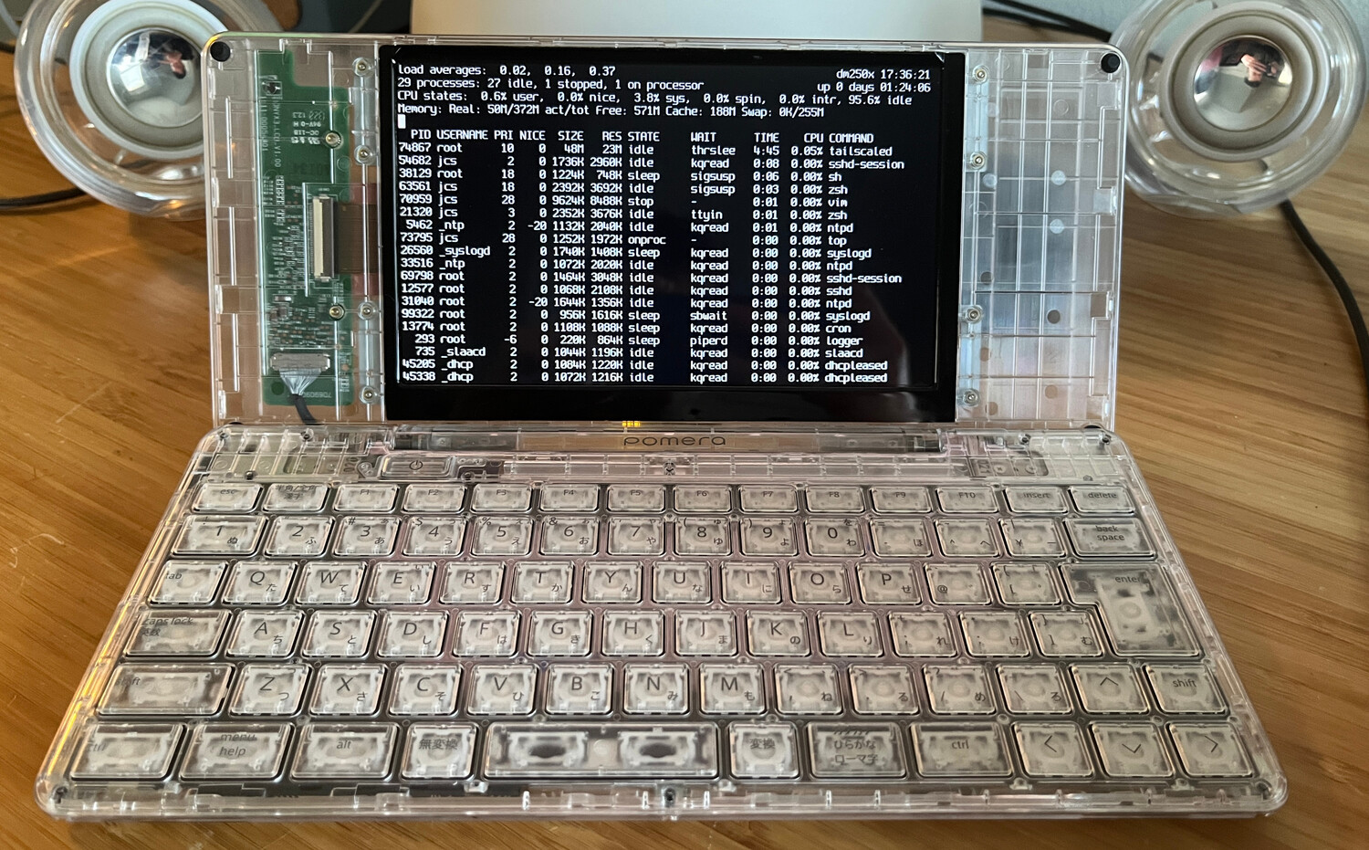
This shows continuous boot output from the EFI bootloader all the way to the
console login, which is nice.
If I enable the video drivers (rklvds, rkvop, rkdrm) to (re-)initialize
the video in OpenBSD, it boots about halfway through the kernel sequence and
then blacks out for a second or two as it has to wait for hardware to settle
before drawing through the new output path.
With video and the keyboard working, I finally reached that point where I could
do development directly on the device which feels a lot different than remotely
poking at something through a serial console.
I've done a lot of little quality-of-life changes like implementing a US
keyboard layout for the non-US model (available with wsconsctl
keyboard.encoding=us), adding
gpio(4)
support to rkgpio so I can poke individual GPIO pins from userland with
gpioctl.
This allows me to turn on and off the red (gpioctl gpio1 8) and green
(gpioctl gpio1 12) LEDs on the side of the device depending on whether the
battery is about to die (red) or is charging (green).
One thing that is odd about the DM250 is that the left Alt key and the right Shift key are directly wired up to their own GPIO pins, not going through the TC35894 like every other key. Presumably this is why the recovery sequence that the vendor's U-boot tree looks for is those two keys plus power, so their U-boot didn't have to implement a TC3589X driver.
Anyway, since those two keys are not on the keyboard, I thought about how to
make them work in OpenBSD without a specific hack for the DM250 or something in
my tcmfd driver that had to reach into GPIO land.
Since the existing OpenBSD gpiokeys driver works on armv7 and sees the entries
in the device tree:
gpiokeys0 at mainbus0: "Power Button", "Lid Switch", "Right Shift", "Left Alt"
I added a
(only-slightly-hackish)
hack
to it to inject unknown GPIO keys into the console wskbd device's input
stream, so anything listening for keyboard input will see left Alt and right
Shift as though it came from the same tc35894 device.
This means Control+Alt+F# keys work as expected to change virtual terminals, for
example.
I still have a laundry list of things I'd like to keep working on like improving the keyboard driver, implementing some degree of suspend/resume, and supporting the external DMA engine for the MMC controller to speed up eMMC access. Our arm port also doesn't enable multiple processors but some degree of support seems there from when it was imported from NetBSD.
My list of commits is getting quite long so I need to try to upstream as much of this as possible. My last attempts at committing just basic RK3128 support in various drivers were thwarted, so I'm still just hammering out stuff in my own trees for now. If you have a DM250 (non-US for now) and want to try OpenBSD on it, let me know and I can send you installation images and instructions.
Note: I am frequently rebasing and squashing commits in my trees as I improve things, so the commit IDs in the trees linked here may vanish or become obsolete.
OpenBSD 7.9-beta (GENERIC) #134: Mon Mar 23 16:10:06 CDT 2026
	jcs@dm250x:/usr/src/sys/arch/armv7/compile/GENERIC
real mem  = 1018015744 (970MB)
avail mem = 988418048 (942MB)
random: good seed from bootblocks
mainbus0 at root: Rockchip RK3128 Pomera DM250
cpu0 at mainbus0 mpidr f00: ARM Cortex-A7 r0p5
cpu0: 32KB 32b/line 2-way L1 VIPT I-cache, 32KB 64b/line 4-way L1 D-cache
cpu0: 256KB 64b/line 8-way L2 cache
cortex0 at mainbus0
syscon0 at mainbus0: "syscon"
"power-controller" at syscon0 not configured
syscon1 at mainbus0: "qos"
syscon2 at mainbus0: "qos"
syscon3 at mainbus0: "qos"
syscon4 at mainbus0: "qos"
syscon5 at mainbus0: "qos"
syscon6 at mainbus0: "qos"
syscon7 at mainbus0: "qos"
ampintc0 at mainbus0 nirq 160, ncpu 4: "interrupt-controller"
rkclock0 at mainbus0
syscon8 at mainbus0: "syscon"
rkusbphy0 at syscon8: phy 0
rklvds0 at syscon8: LVDS 24-bit JEIDA
rkpinctrl0 at mainbus0: "pinctrl"
rkgpio0 at rkpinctrl0
gpio0 at rkgpio0: 32 pins
rkgpio1 at rkpinctrl0
gpio1 at rkgpio1: 32 pins
rkgpio2 at rkpinctrl0
gpio2 at rkgpio2: 32 pins
rkgpio3 at rkpinctrl0
gpio3 at rkgpio3: 32 pins
rkdrm0 at mainbus0
drm0 at rkdrm0
agtimer0 at mainbus0: 24000 kHz
rkvop0 at mainbus0: RK3126 VOP
dwctwo0 at mainbus0
dwmmc0 at mainbus0: 49 MHz base clock
sdmmc0 at dwmmc0: 4-bit, sd high-speed, mmc high-speed
dwmmc1 at mainbus0: 49 MHz base clock
sdmmc1 at dwmmc1: 4-bit, sd high-speed
dwmmc2 at mainbus0: 49 MHz base clock
sdmmc2 at dwmmc2: 8-bit, mmc high-speed
rklvdsphy0 at mainbus0
dwdog0 at mainbus0
rkpwm0 at mainbus0
com0 at mainbus0: dw16550, 64 byte fifo
bcmbt0 at com0
com1 at mainbus0: dw16550
rkiic0 at mainbus0
iic0 at rkiic0
tcmfd0 at iic0 addr 0x45
wskbd0 at tcmfd0: console keyboard
rkpmic0 at iic0 addr 0x1c: RK818
rkcharger0 at rkpmic0: 4.2V 5800mAh battery
simplebat0 at rkcharger0
gpioleds0 at mainbus0: "pomera:green:power"
gpiokeys0 at mainbus0: "Power Button", "Lid Switch", "Right Shift", "Left Alt"
pwmbl0 at mainbus0
simplepanel0 at mainbus0: 1024x600
rkdrm0: 1024x600, 32bpp
wsdisplay0 at rkdrm0 mux 1: console (std, vt100 emulation), using wskbd0
wsdisplay0: screen 1-5 added (std, vt100 emulation)
usb0 at dwctwo0: USB revision 2.0
uhub0 at usb0 configuration 1 interface 0 "DWC2 DWC2 root hub" rev 2.00/1.00
addr 1
scsibus0 at sdmmc0: 2 targets, initiator 0
sd0 at scsibus0 targ 1 lun 0: <Sandisk, SD32G, 0085> removable
sd0: 30436MB, 512 bytes/sector, 62333952 sectors
scsibus1 at sdmmc2: 2 targets, initiator 0
sd1 at scsibus1 targ 1 lun 0: <Toshiba, 008GB0, 0000> removable
sd1: 7456MB, 512 bytes/sector, 15269888 sectors
bwfm0 at sdmmc1 function 1
manufacturer 0x02d0, product 0xa9a6 at sdmmc1 function 2 not configured
vscsi0 at root
scsibus2 at vscsi0: 256 targets
softraid0 at root
scsibus3 at softraid0: 256 targets
bootfile: sd0a:/bsd
boot device: sd0
root on sd1a (717a8af462695010.a) swap on sd1b dump on sd1b
bcmbt0: address 70:4a:0e:df:xx:xx
bwfm0: address 70:4a:0e:df:xx:xx