iMac G4(K)
A year ago I tried using an M1 iMac for work duty but its 21" screen took up too much room on my desk. After seeing Sean's video on Action Retro about putting an M4 Mac Mini inside an iMac G4, I thought I'd give it a try.
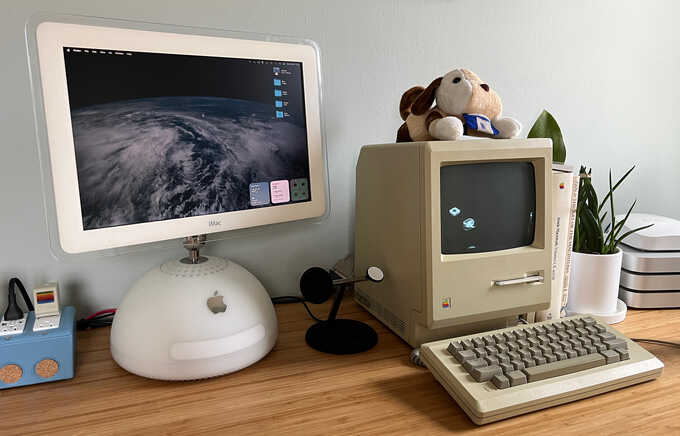
Table of Contents
Trying the Juicy Crumb DockLite G4
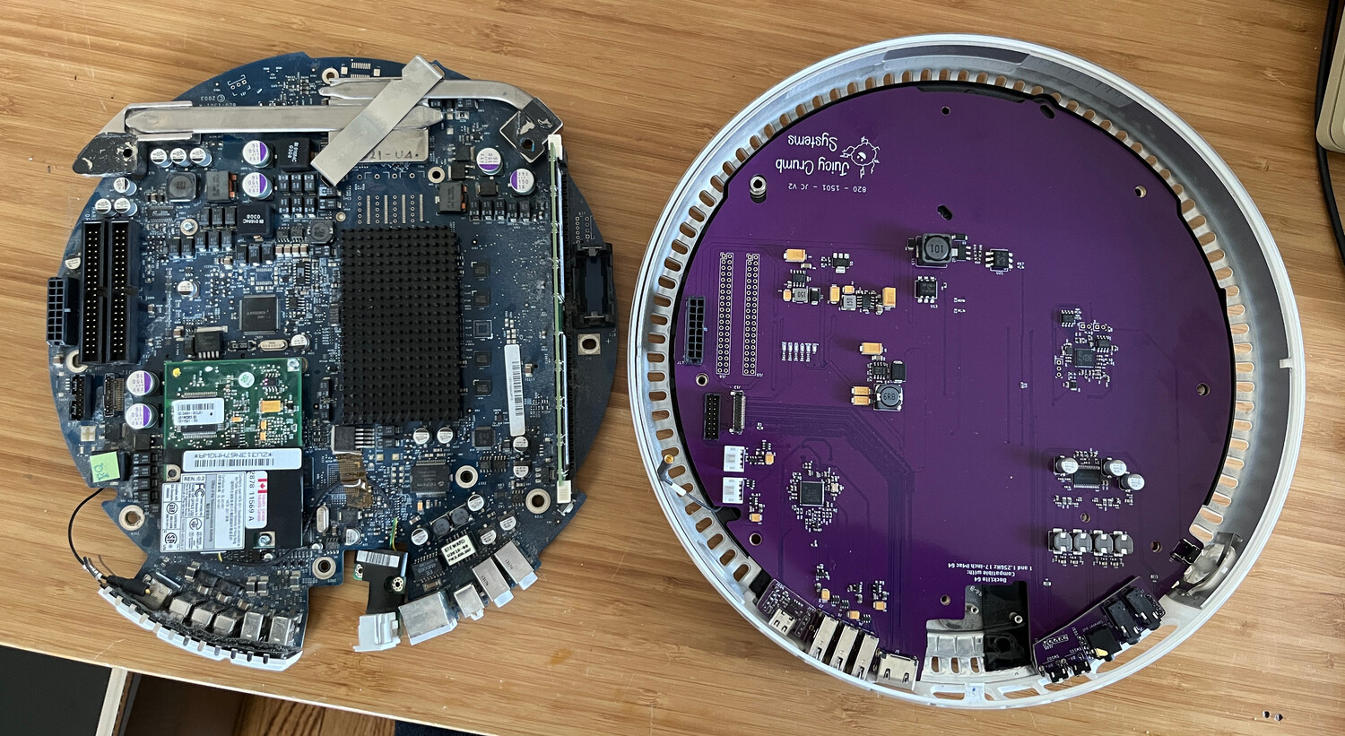
The Juicy Crumb DockLite G4 replaces the main logic board in a 17" or 20" iMac G4 and turns its built-in LCD into an HDMI monitor. It also uses the iMac's custom power supply and has a built-in audio amplifier to be able to drive the Apple Pro speakers that were available for the iMac G4. Swapping the boards is easy and completely reversible.
I ordered the DockLite G4 but it was going to take a few weeks to get. In the mean time, I needed to find a 17" iMac G4 in good condition but not fully working so that I wouldn't be sacrificing a working machine. I eventually found one on eBay and I paid nearly as much for shipping as the machine itself. The iMac uses a lot of thick steel inside the dome which makes it quite heavy.
Pro tip: there are a bunch of 17" G4 iMacs on eBay that are listed as 15". I don't know if it's because eBay fills this in by default or if people are confused by the screen size since it measures about 15" horizontally but the 17" refers to its diagonal size. It's usually possible to tell which size it is by the photos since the 15" looks much more square, but if you can get the serial number on the bottom, looking it up will confirm whether it's 15" or 17".
Once the dead iMac arrived, a power-on test produced a happy chime but showed nothing on the screen. At this point I wasn't sure if the LCD was busted or if the problem was with the iMac's logic board, so I had to get a Mini VGA to VGA adapter to test its video output. This also failed to show any video so I was pretty sure the logic board was faulty but I still had no idea whether the LCD worked.
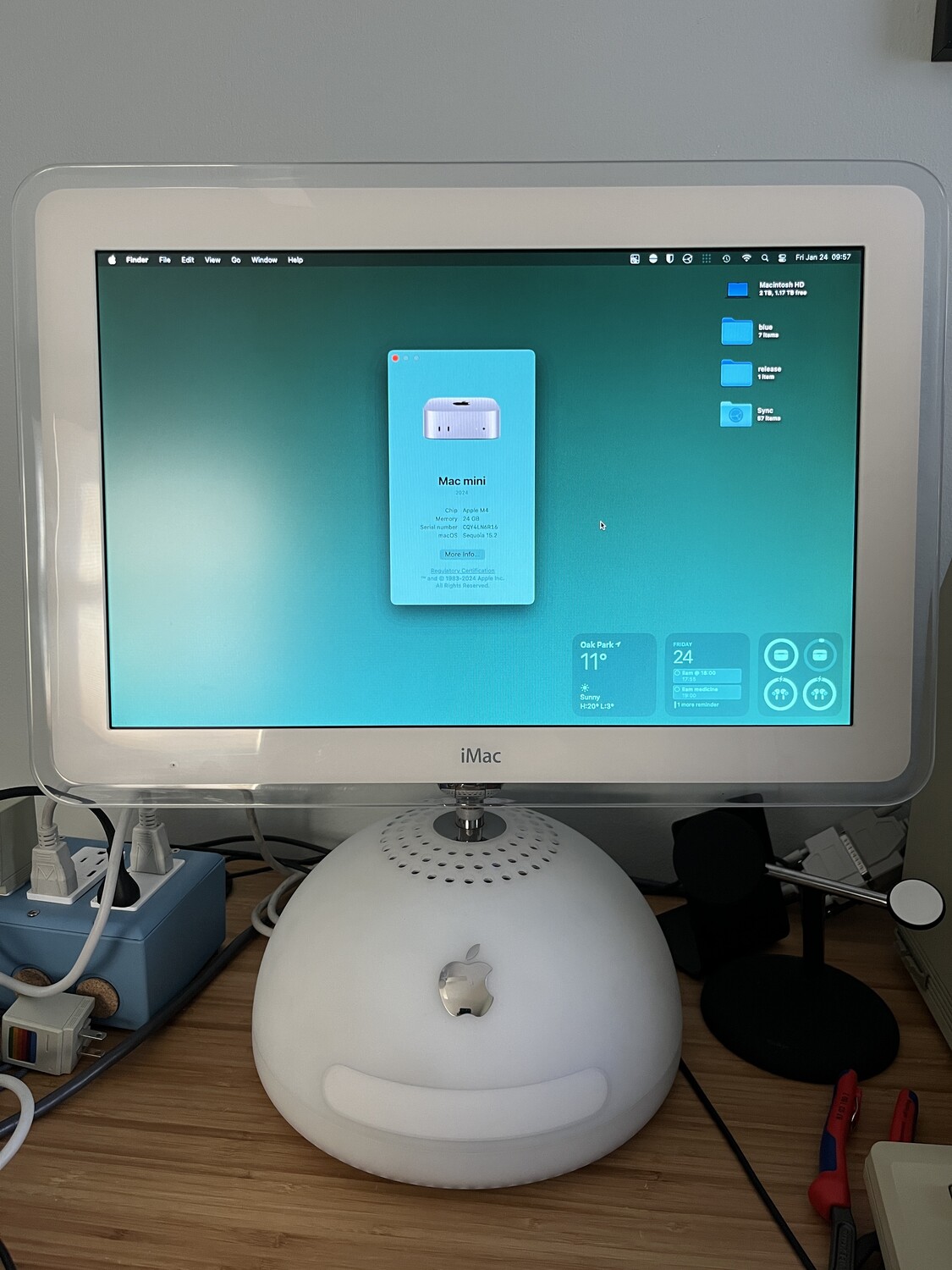
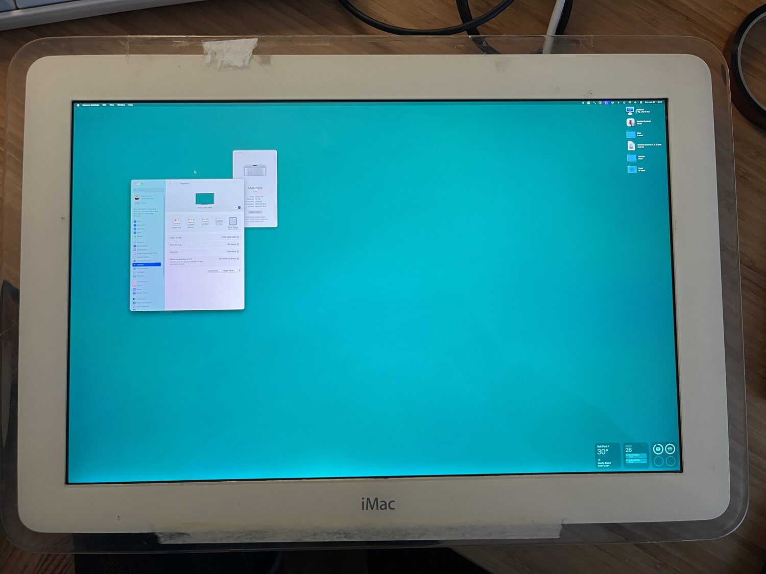
Eventually the DockLite arrived from Australia and after a few minutes of swapping things, I was able to confirm that the LCD worked fine and was displaying the Mac Mini's desktop over HDMI.
Unfortunately after using the iMac for a little while, I noticed a few issues that soured my experience with the DockLite.
Color Banding
I'm not sure whether the DockLite or the 20-year old LCD screen is to blame for this, but there is noticeable color banding on the screen, especially with macOS window shadows.
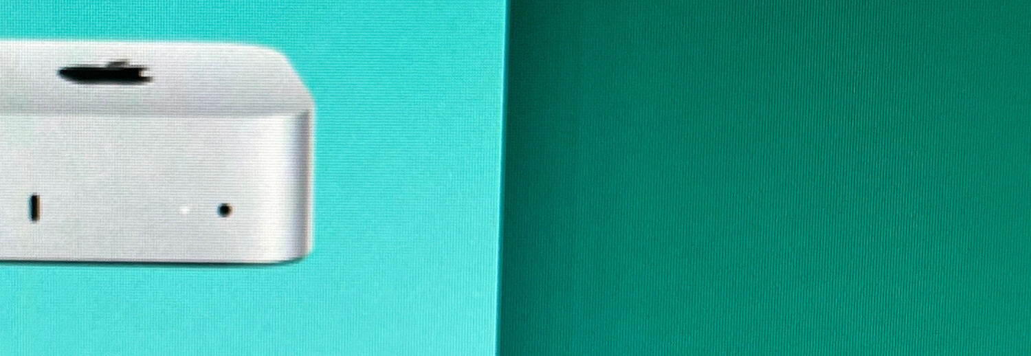
I wasn't able to test native Mac OS with the iMac's logic board so I can't be sure the problem isn't with the LCD, but I've seen this same problem with some other generic LVDS/eDP to HDMI boards.
iMac Screen Resolution
My other issue with using the iMac G4 was that its 17" screen has a resolution of only 1440x900. This isn't terrible but having used 1.5x or 2x resolution screens on my laptops for many years, the small resolution was not ideal and modern macOS is definitely not tuned for 1x resolutions anymore.
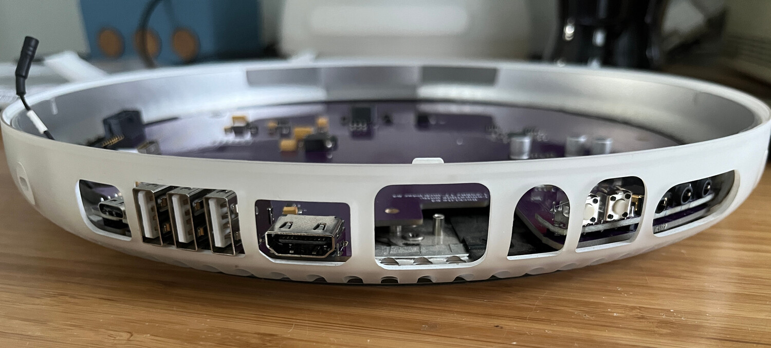
Exposed Ports
It's a very minor gripe, but I would have liked some sort of covers to fill in the space between the DockLite's new ports (or lack thereof) and the iMac's bottom case cutouts. No one's going to see them anyway but for the money, it would have been nice to have that included.
Screen Blanking
However, my biggest issue with the DockLite is that it doesn't support turning off the display via HDMI (DPMS or CEC or whatever this is). When the Mac Mini tries to blank the screen after inactivity, the DockLite keeps the backlight on showing a black screen. Juicy Crumb warns about this in the documentation saying to tap the power button on the back of the iMac (which pushes the power button on the DockLite board) to turn off the screen since leaving it on all the time will damage it. This was going to get pretty annoying since I would like to leave the machine on all the time but I wouldn't be using it very often, so I would like the display to turn off and back on automatically when I need it.
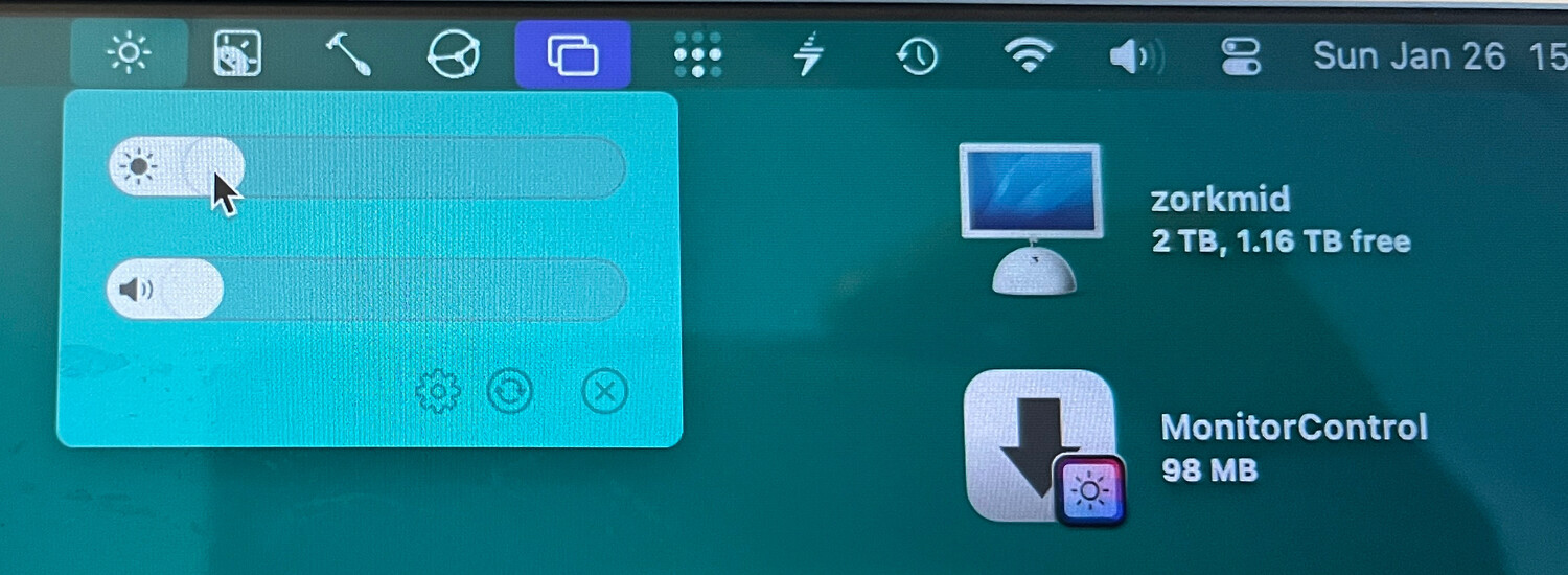
On the upside, the DockLite does support adjusting the LCD's backlight level via USB through a custom macOS application rather than having to press the buttons on the back of the iMac.
Upgrading the Screen
With these faults in mind, I decided to ditch the DockLite and go with a custom screen upgrade. With a different LCD and appropriate driver board, I could get a higher resolution with better color and gain screen blanking. By eliminating the DockLite, I could then remove the iMac's internal power supply which otherwise takes up a large portion of the upper part of the dome. That would then free up enough room inside the iMac to store the Mac Mini without modifying it (as Sean had to in his YouTube video).
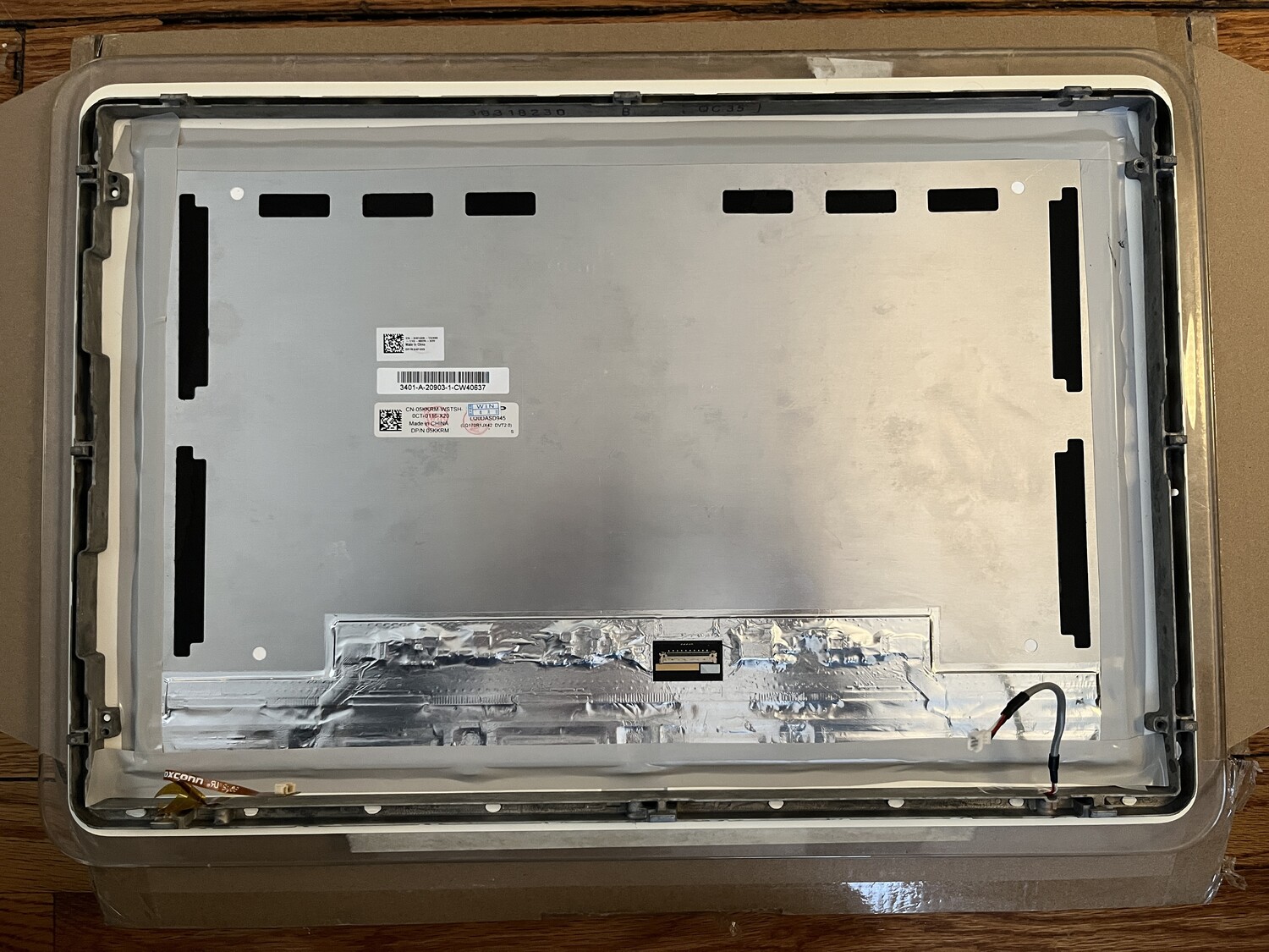
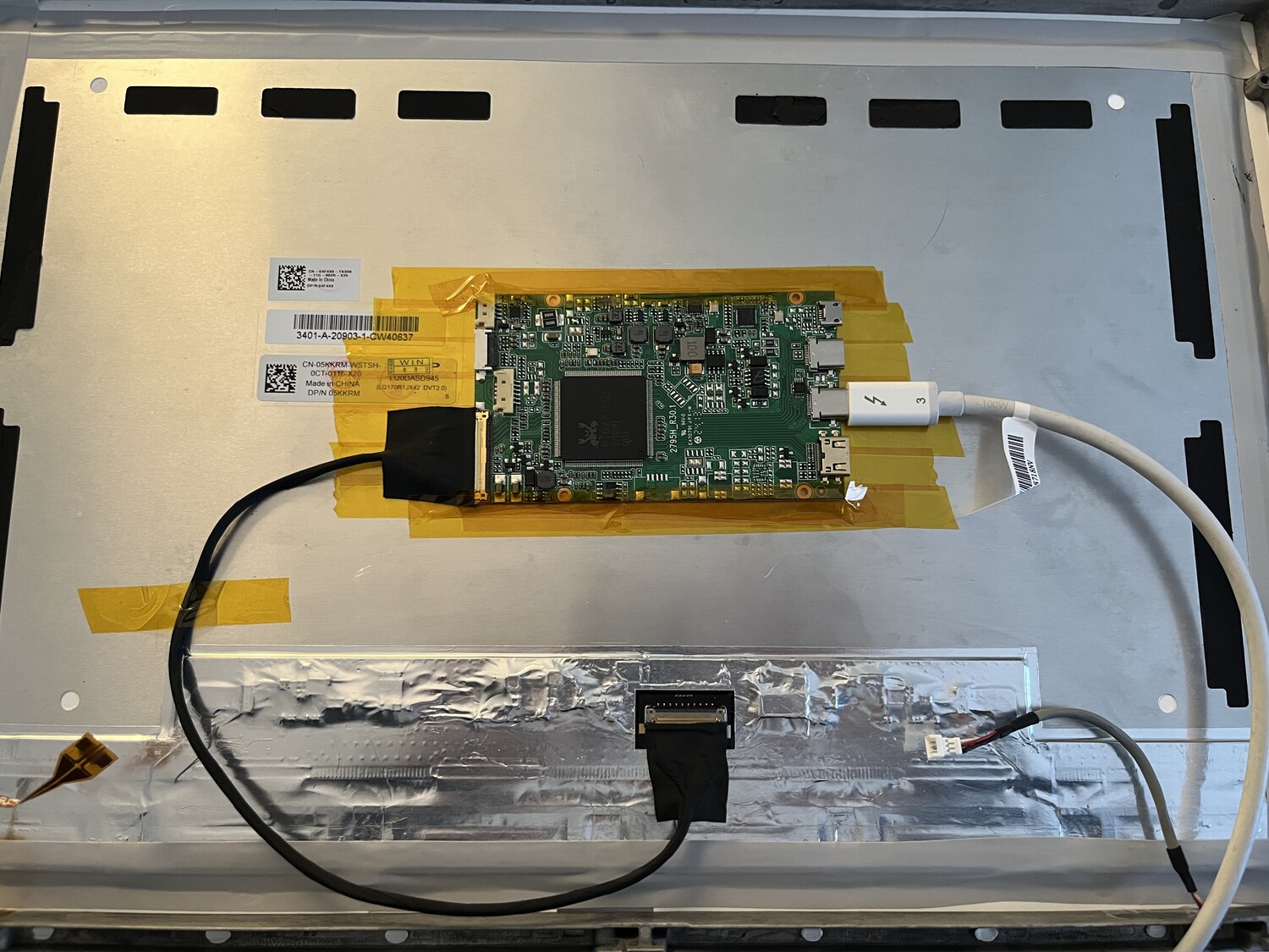
Browsing eBay, I found the Sharp LQ170R1JX42, a 4K 3840x2400 17" LCD originally used in the Dell XPS 17. This would provide a 2x resolution of 1920x1200 in the same outer footprint of the iMac's original LCD and fit behind the screen bezel. An appropriate eDP driver board would connect the LCD to the Mac Mini over HDMI or USB-C.
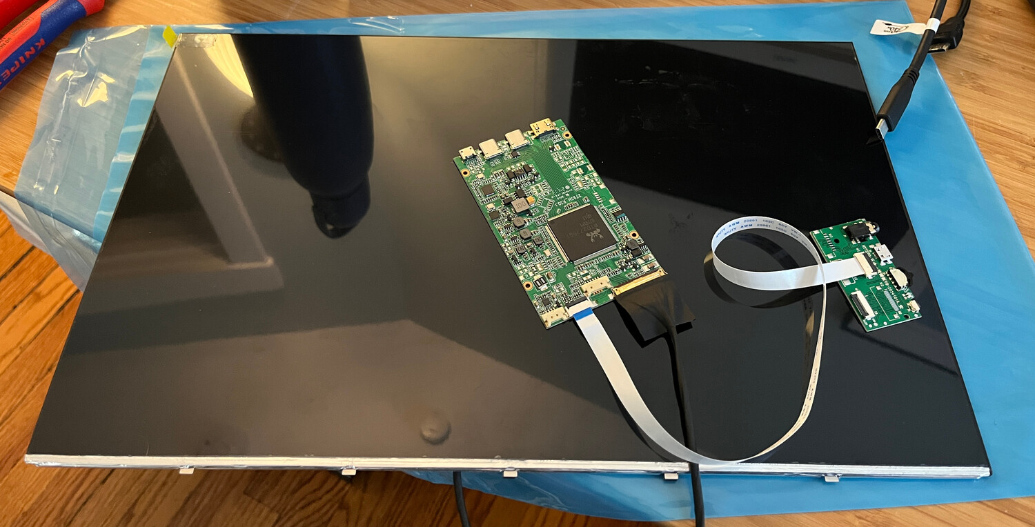
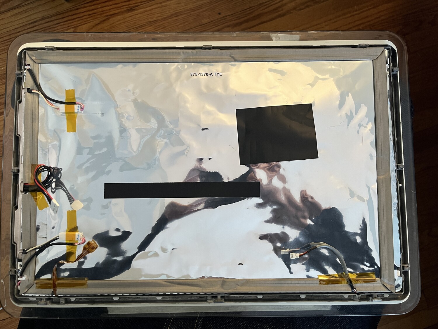
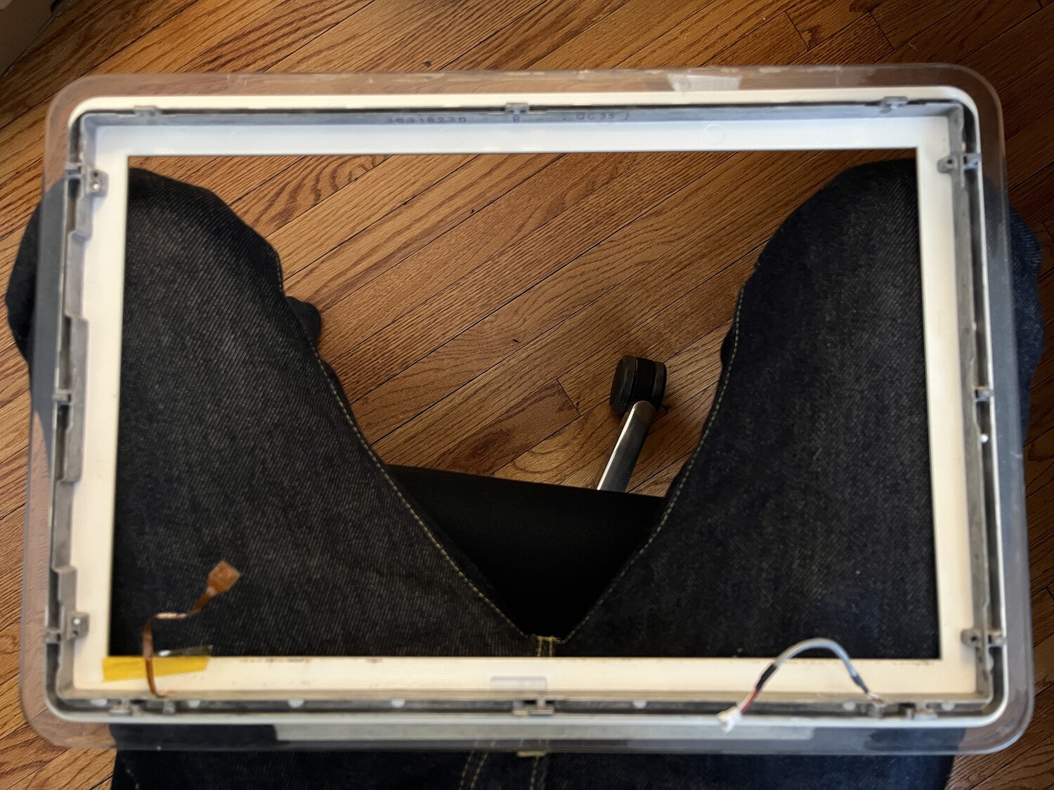
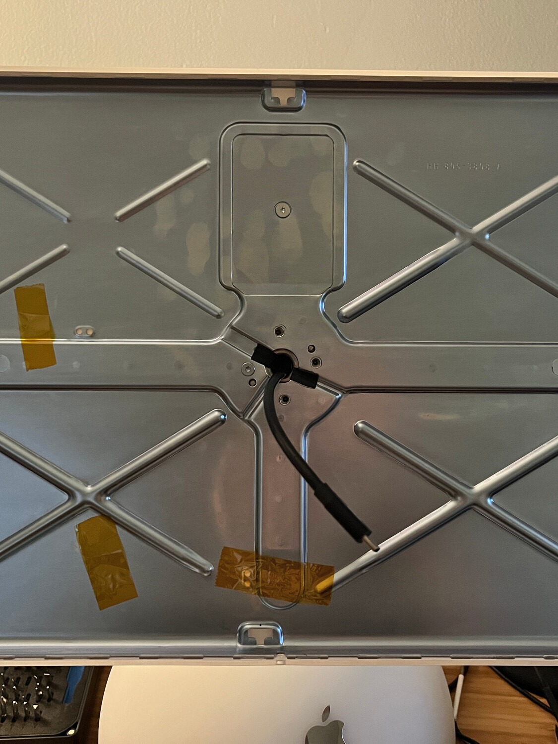
Once I confirmed the new LCD and driver worked with the Mac Mini, I disassembled the iMac to swap its screen. The original LCD is quite heavy and is about 1/2" thick due to its CCFL backlight. The new LCD with its LED backlight is so light and thin, I didn't even bother making a frame to attach it to the bezel, I just secured it with tape and then mounted the controller to the back of it.
Running at its native 3840x2400 resolution shows how fine its dot-pitch is, though I am now running it at 2x:
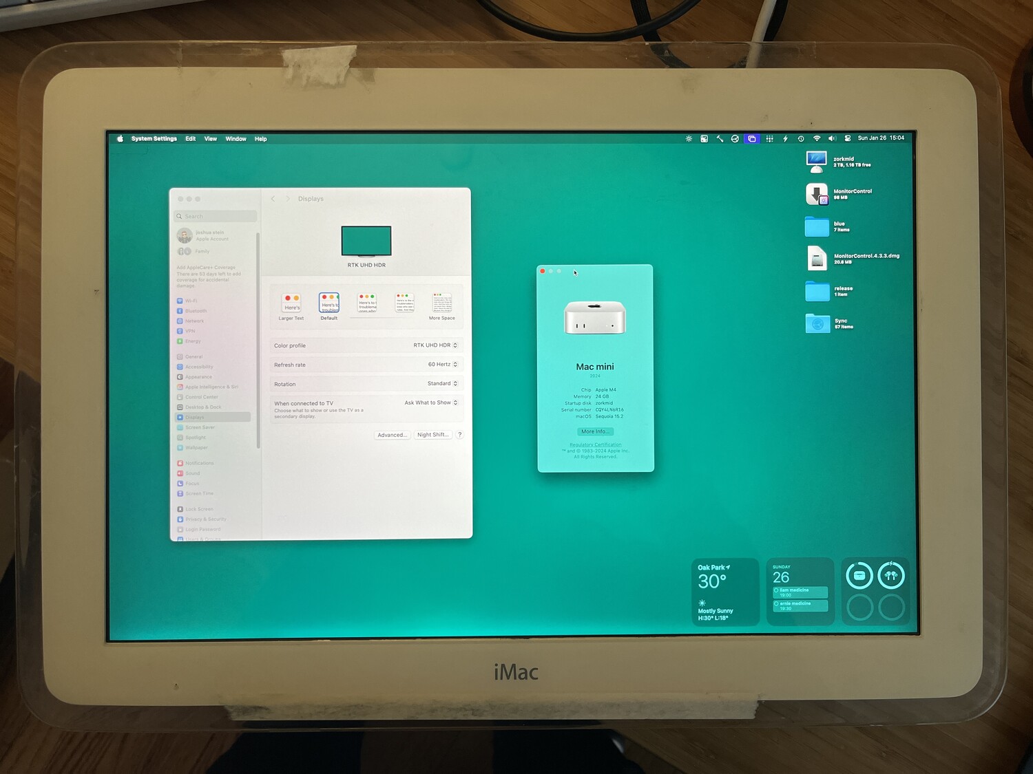
Using the MonitorControl utility, I could change the LCD backlight level from software, and the eDP board automatically powers off the LCD when the Mac Mini tells it to sleep, unlike the DockLite.
iMac Neck
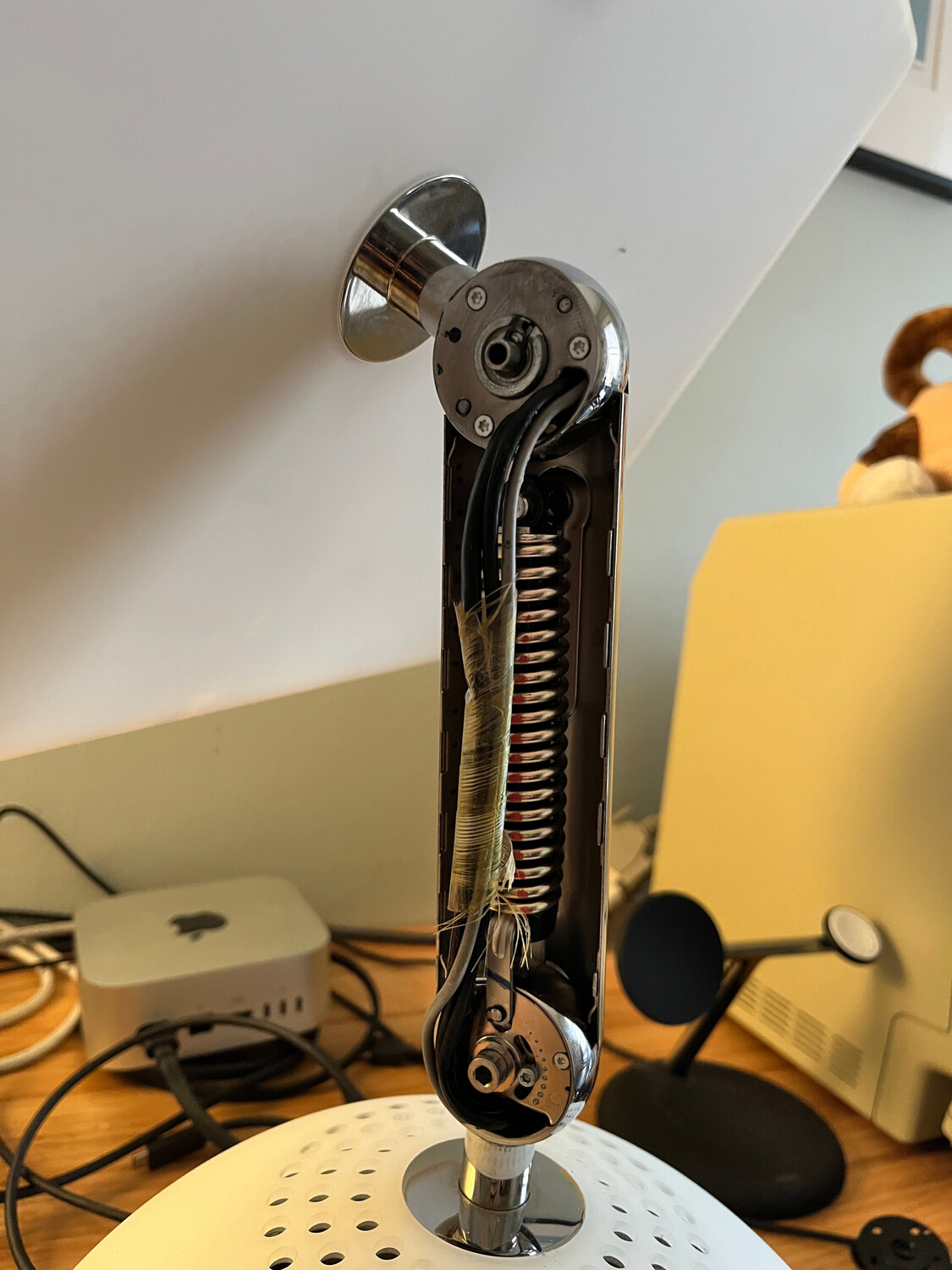
Once the new LCD was working over USB-C, I ran into the problem of having to get the new cable run inside of the iMac's articulating neck. The cables connecting to the original LCD are run inside the neck assembly during manufacturing and then connectors are added afterward since they are too large to fit through the small openings at the top and bottom of the neck. Unfortunately this meant I had to cut these original cables to get them out, and it also made it difficult to run a USB-C cable through it.
The smallest diameter of the neck hinge is about 9mm where it meets the dome, but most USB-C/Thunderbolt cables I tried had at least a width of about 12mm. Even after trimming off the rubber/silicone of some of them, they often had a PCB or other stuff inside that was wider than the connector.
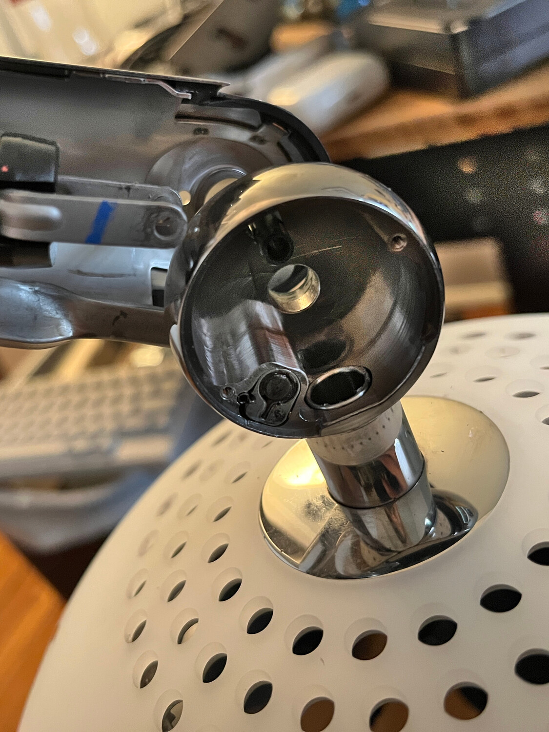
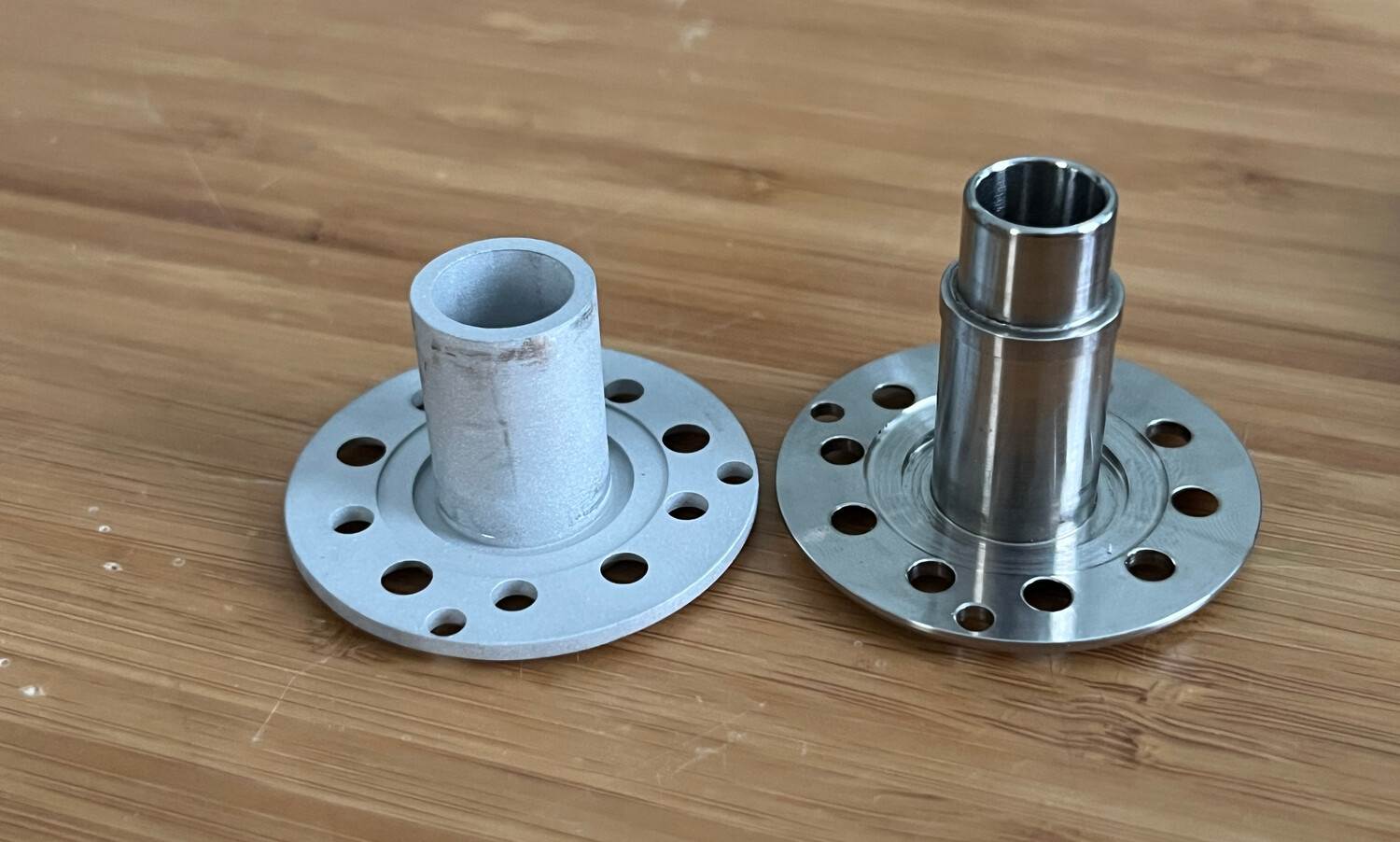
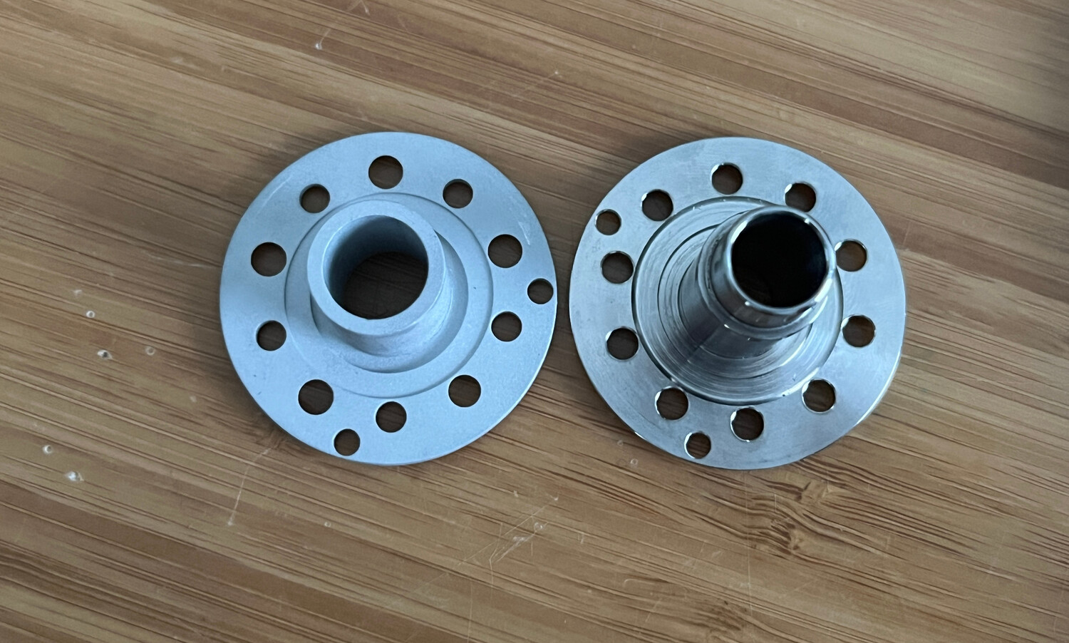
The 9mm opening is on a flange that slides inside the base of the neck and is where the dome attaches to the neck with 5 screws. It tapers to a smaller opening at the top because there is usually a sleeve that goes around it to make rotating smoother, though it's not really needed in my experience. I figured I could make a new piece like it and make it not taper, allowing the inner wall to be thinner and its opening wider, ultimately allowing the USB-C cable to pass through it.
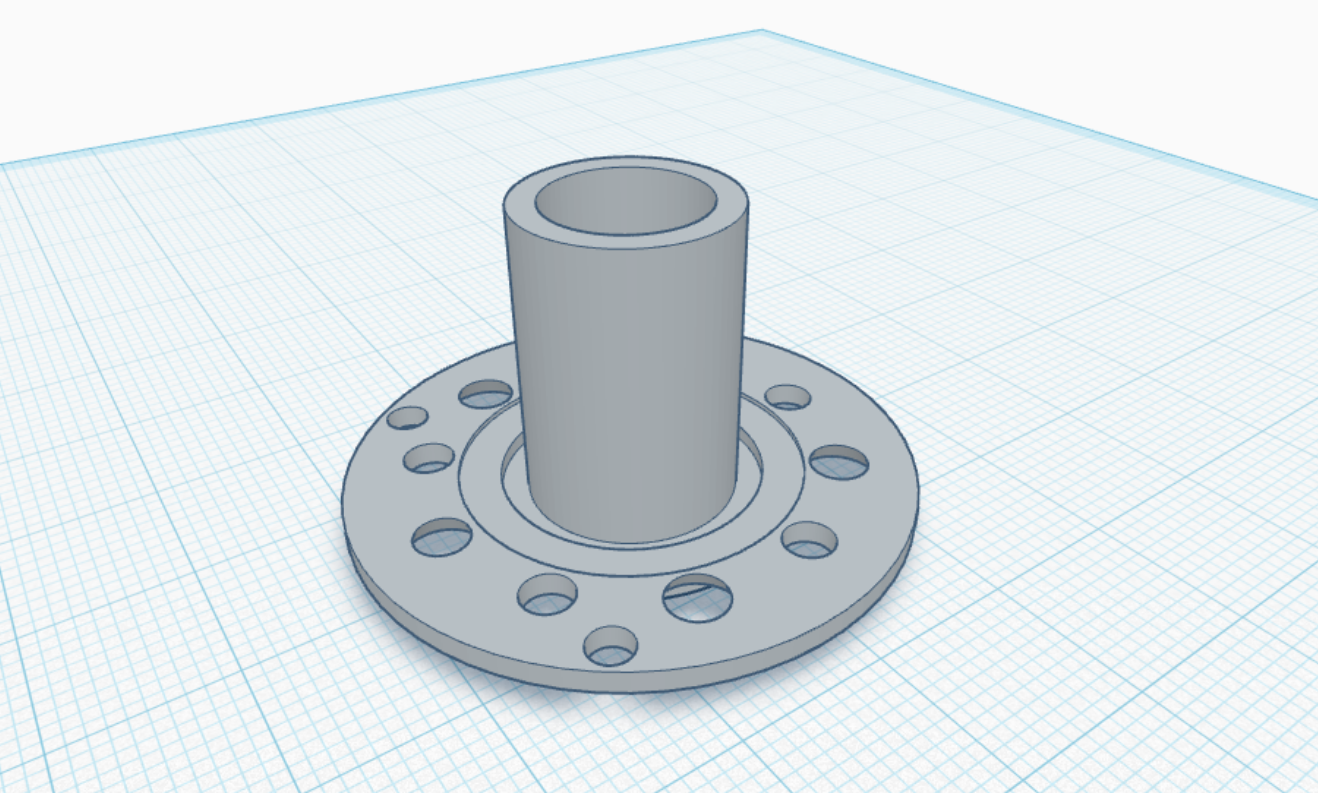
I took some measurements and modeled the flange in Tinkercad, then did a bunch of 3D prints making tiny adjustments each time. I suppose I'm more of a "measure once, cut 14 times" person.
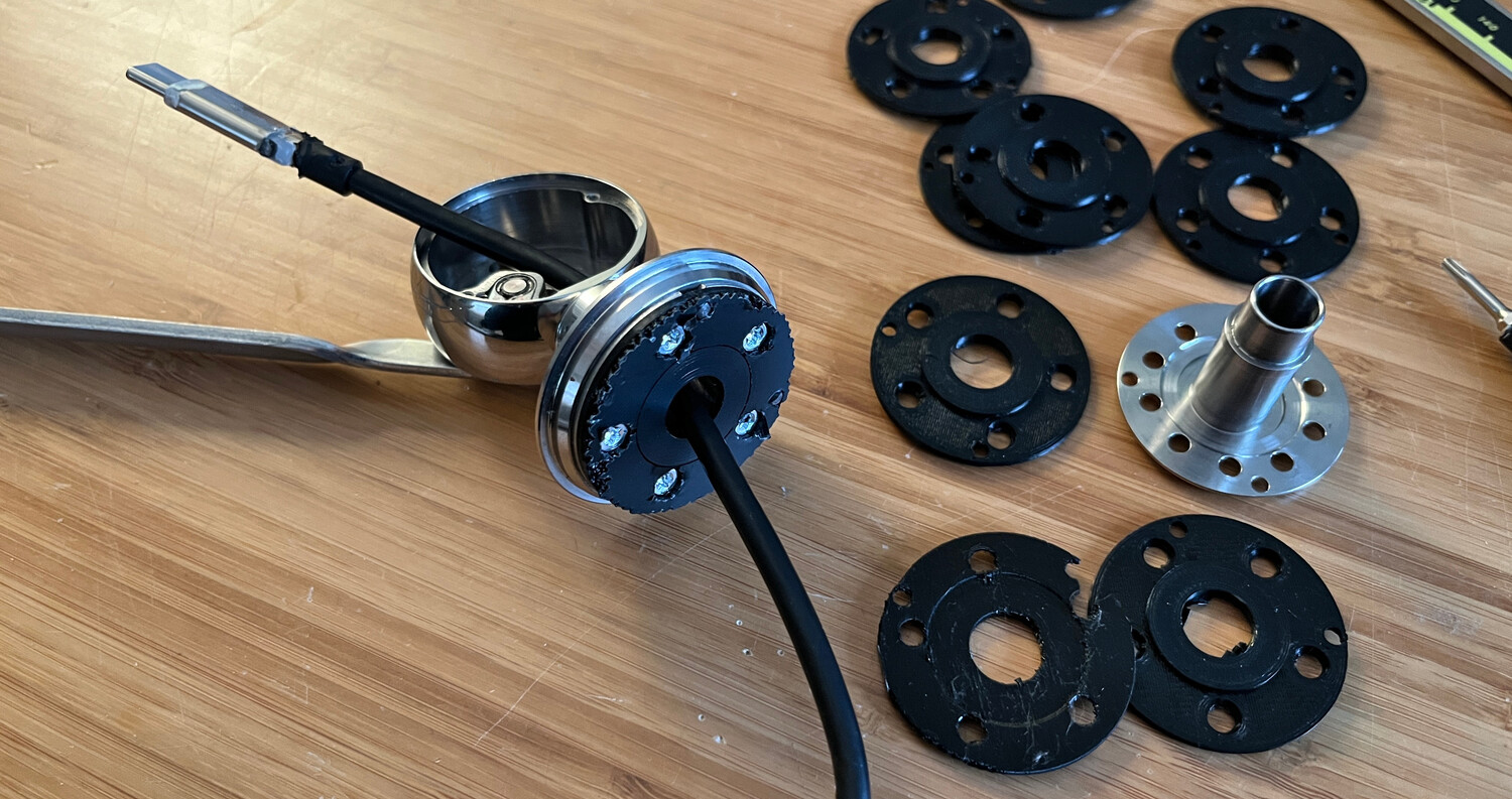
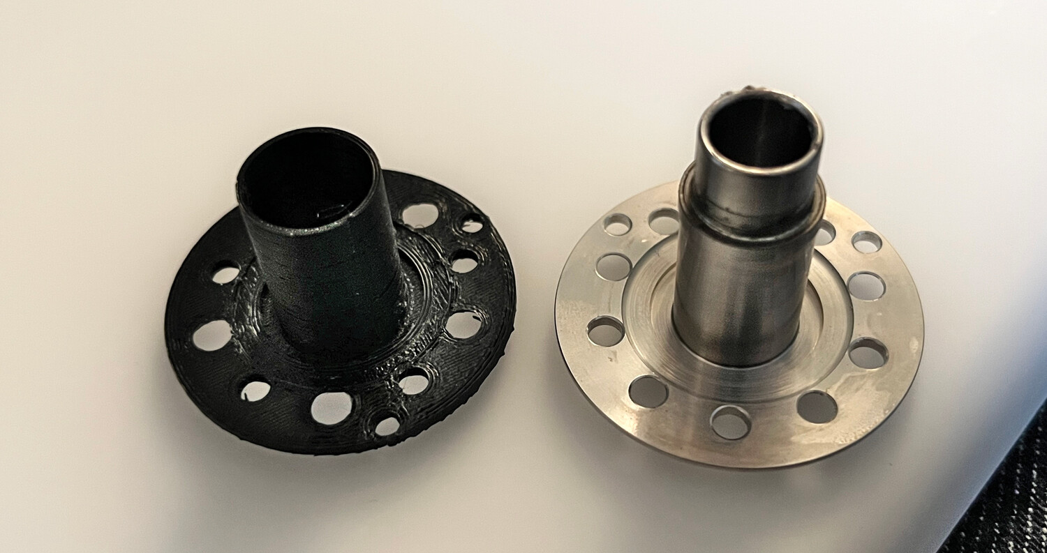
Although it's not load bearing (it is sandwiched between the steel openings at the top of the dome and bottom of the neck assembly), I wanted the new flange to be made out of something stronger than my 3D printer could produce. Once my prototyping was done, I sent the design off to JLCCNC to get it machined out of 6061 aluminum. Their engineer said the thin wall of the vertical tube had to be thicker to get safely machined, so although the opening ended up not being as wide as I wanted, it still allowed a USB-C cable to pass through.
It took a few weeks to machine since I was doing this during Chinese New Year. Although I didn't like the bead-blasted finish which immediately scuffed up, it fit perfectly and the dome could securely attach to the neck.
Update: My designed part can now be ordered directly from PCBWay.
Once I trimmed off some excess rubber from the end of a Thunderbolt cable, I was able to route it through the opening in the rear of the screen housing, down the neck, through the new flange, and into the dome. I then added some shrink tubing to the connector to replace the removed rubber.
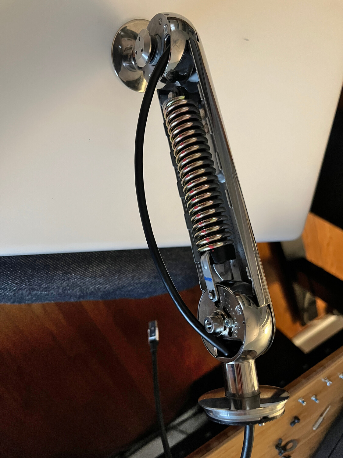
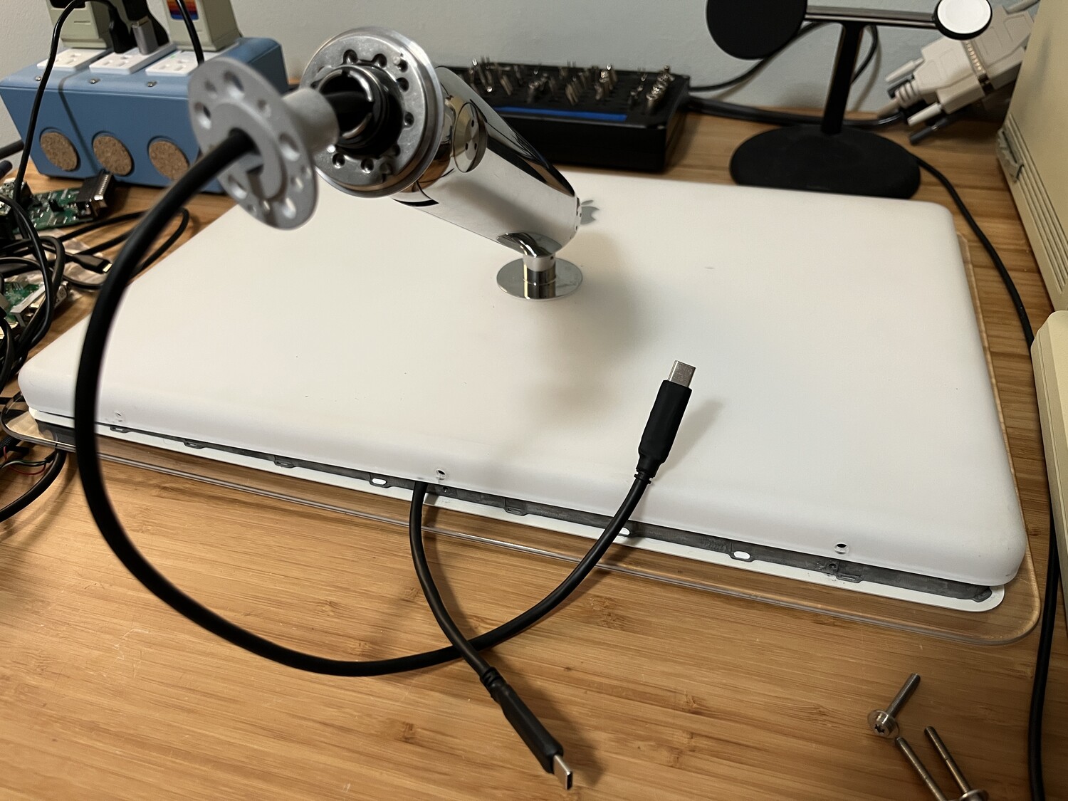
It was important to keep a bit of slack in the cable through the neck to make sure its articulation still worked.


Mac Mini Mouting
Once the top was all put back together, I could now focus on mounting the Mac Mini inside the dome.
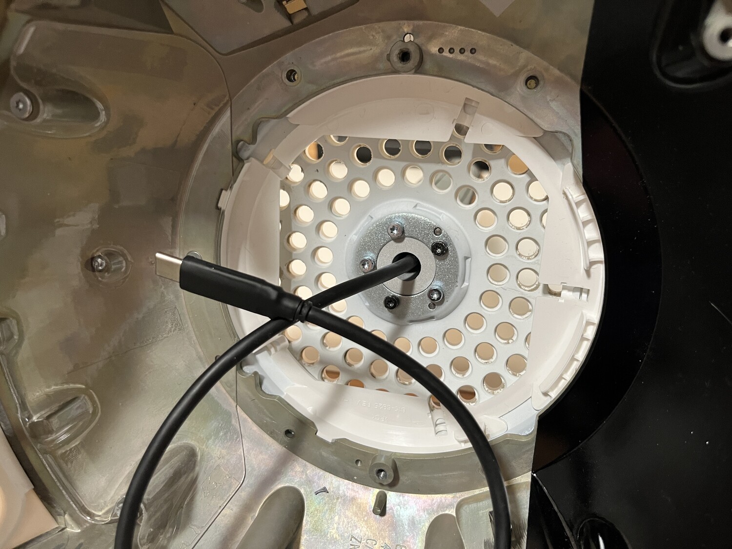
I modeled a new circular piece to replace the Juicy Crumb DockLite board and then added a cross piece to secure the Mac Mini. I was limited by my 3D-printer's build plate dimensions so I had to chop off the bottom of the circle, but there were no mounting holes in that area anyway. I 3D-printed it, inserted heatserts into the cross piece, and bolted down the Mac Mini:
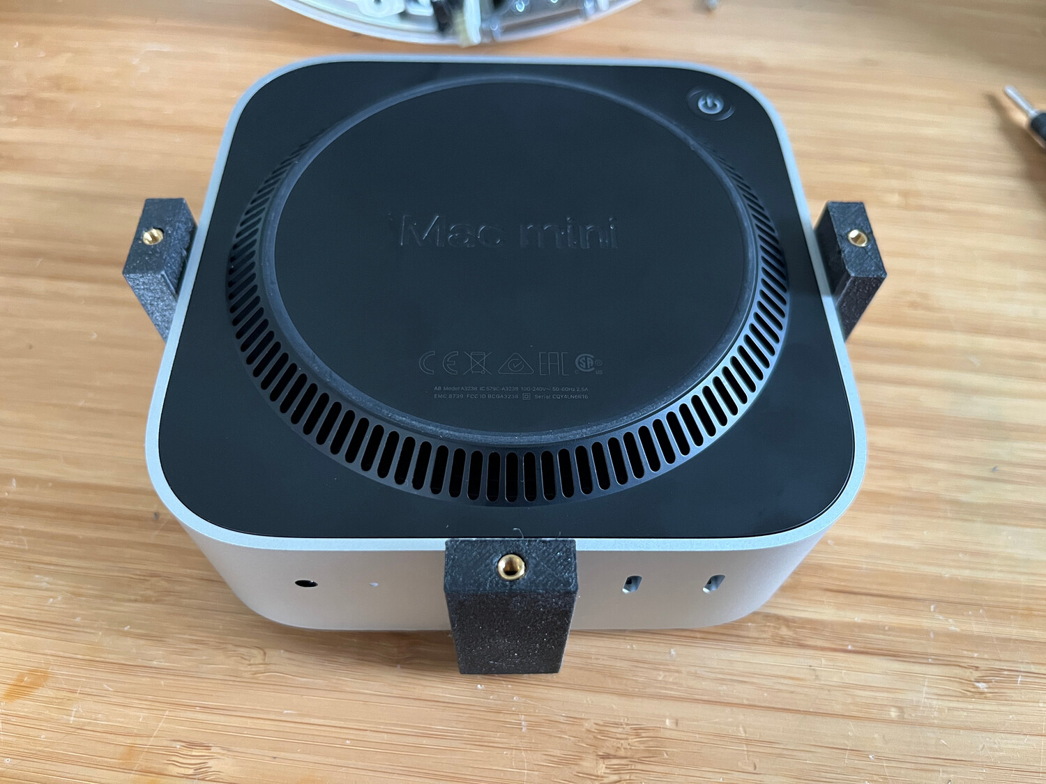

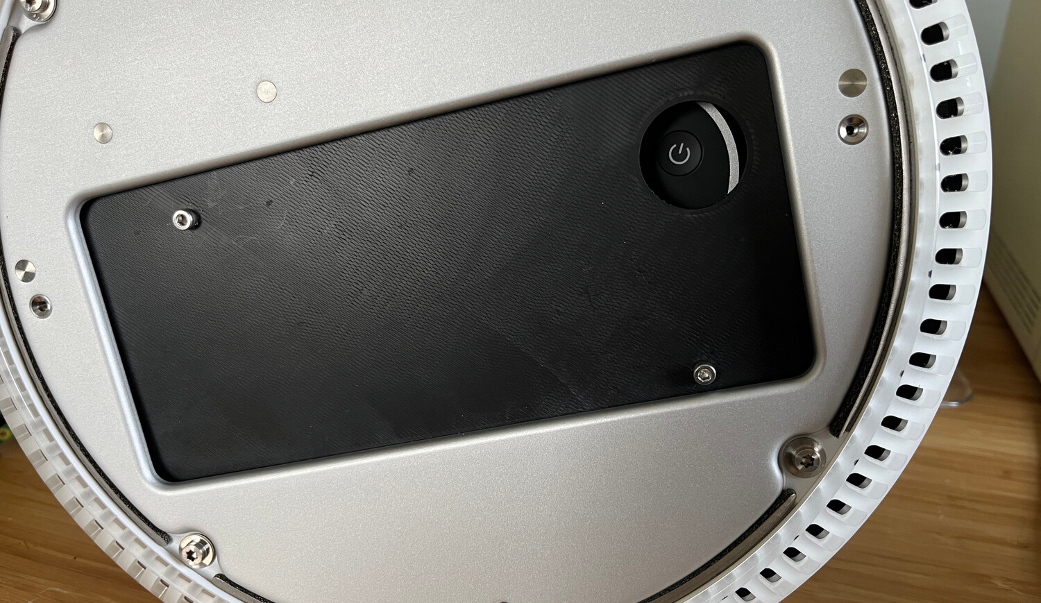
While every tech reviewer complained about the M4 Mac Mini's power button being moved to the bottom, it was actually beneficial to me when putting it inside the iMac. Underneath the iMac is a removable panel that originally gave access to the upgradeable RAM and AirPort slots, but I no longer need it.
By mounting the Mac Mini rotated a bit, the power button is now accessible from the bottom of the iMac and can be pressed just by tilting up the left side of the iMac a bit. Since I would only need to press this button on rare occasions, I figured this would be easier than having to disassemble the Mac Mini to solder an external power button to it.
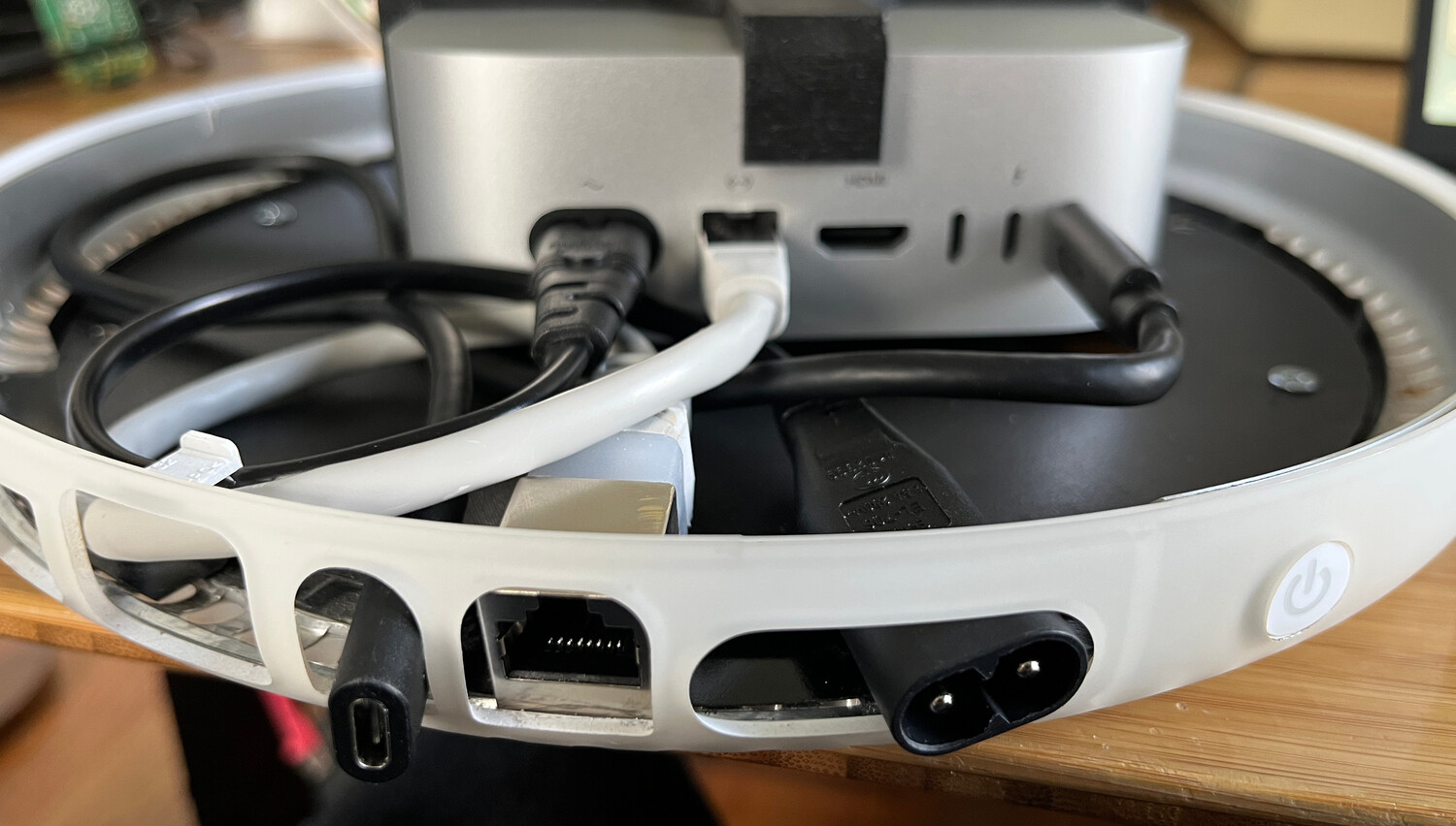
I didn't want to have to open the iMac to reach certain ports, so I bought some short extension cables for the IEC C7/C8 power port, ethernet, and one Thunderbolt port. For now they are just slightly hanging out the back but I'd like to 3D print some sort of bracket to hold them all in place just behind the port openings and fill in the voids.
Remaining Issues
Aside from having to make the rear port bracket, I thought it also might be neat to make use of the flip-down optical drive door to put some USB ports behind it.
The eDP LCD controller currently has an annoying "feature" where once the
display goes to sleep, it shows a blue screen with "No Signal" shown for about
10 seconds before completely shutting off.
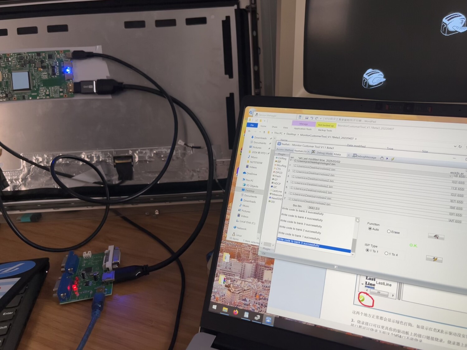
Update: I received a new firmware file from the vendor and was able to flash it with their programming board over HDMI. The blue screen with "No Signal" is now gone and the display immediately goes to sleep when instructed.
If you're purchasing an eDP controller board, I would recommend just asking the vendor to disable that functionality when flashing the board.
Update: Speakers
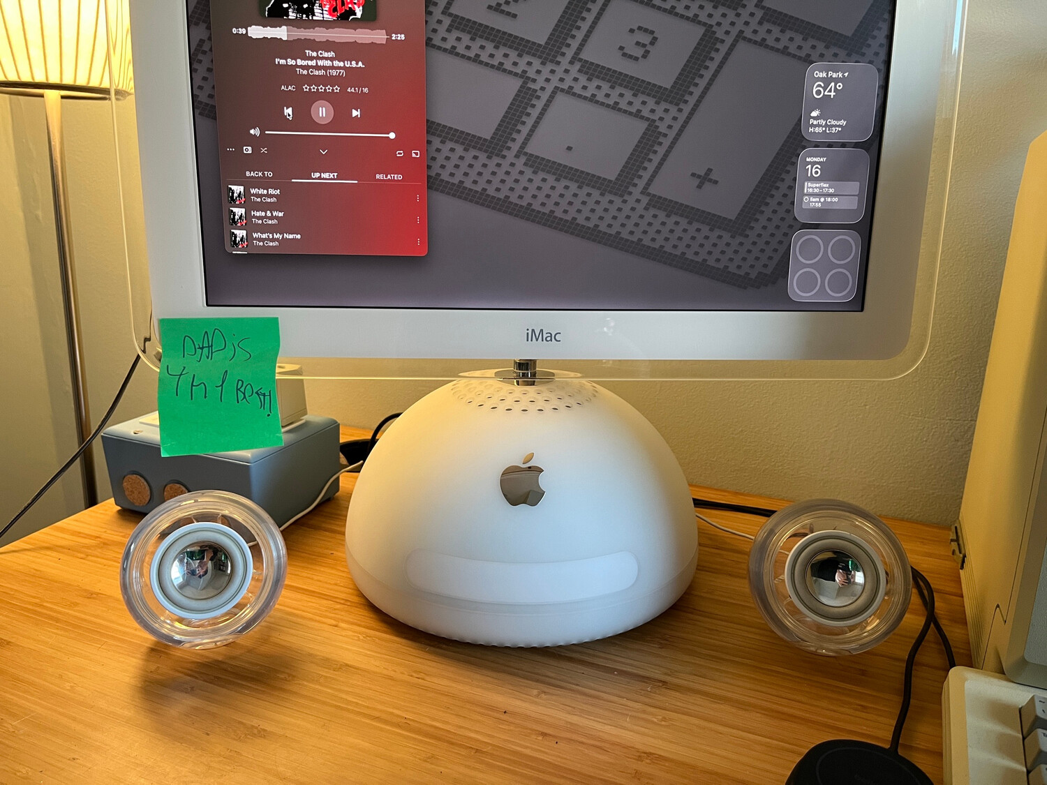
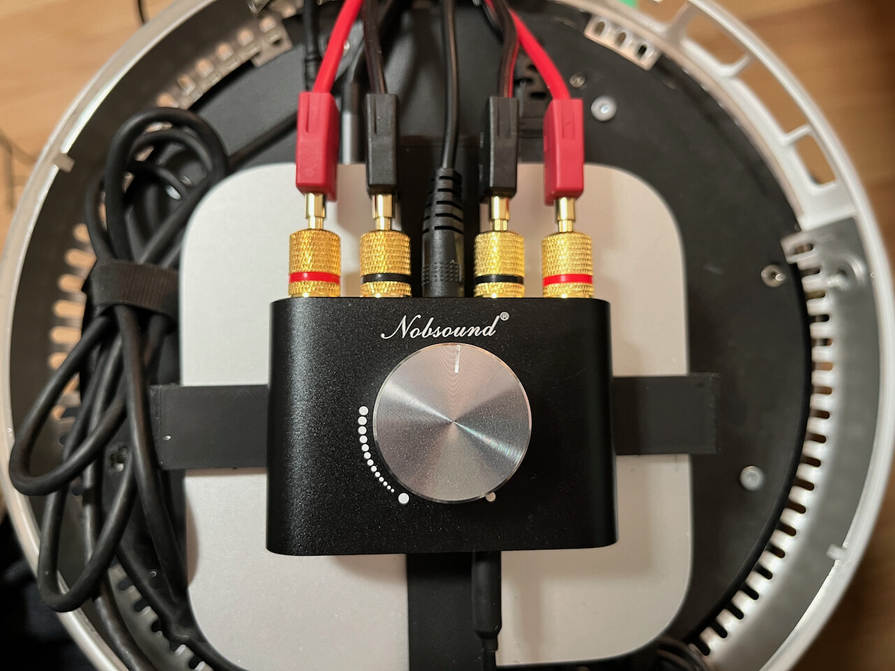
In early 2026 I purchased a clean pair of late-model (the ones with beige rubber gaskets instead of the black foam ones that deteriorate) Apple Pro Speakers on eBay. Since Juicy Crumb's JC Hi-Fi was not available, I had to resort to cutting off the 2.5mm connector and splicing in RCA plugs to each of the 4 wires. I mounted a small amp inside the shell with RCA jacks coming out of it, along with a pigtail for the amp's AC adapter. This way all of the cables could be plugged in outside of the unit so if I needed to move it around, I wouldn't need to open it again.
I initially purchased this amp because it was small and had USB output but it was acting weird when adjusting the volume from mac OS, so I ended up just connecting it to the headphone port with the included 3.5mm cable. I'm sure the sound is warmer now.