Table of Contents
Back to WiFiStation Documentation
WiFiStation Assembly
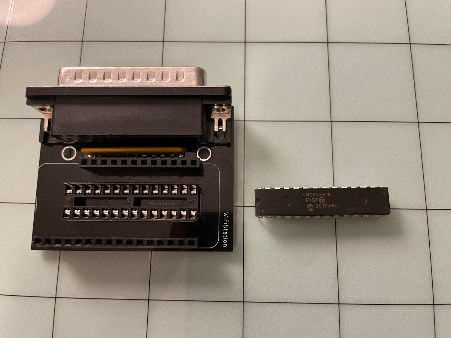
Step 1: Verify Parts
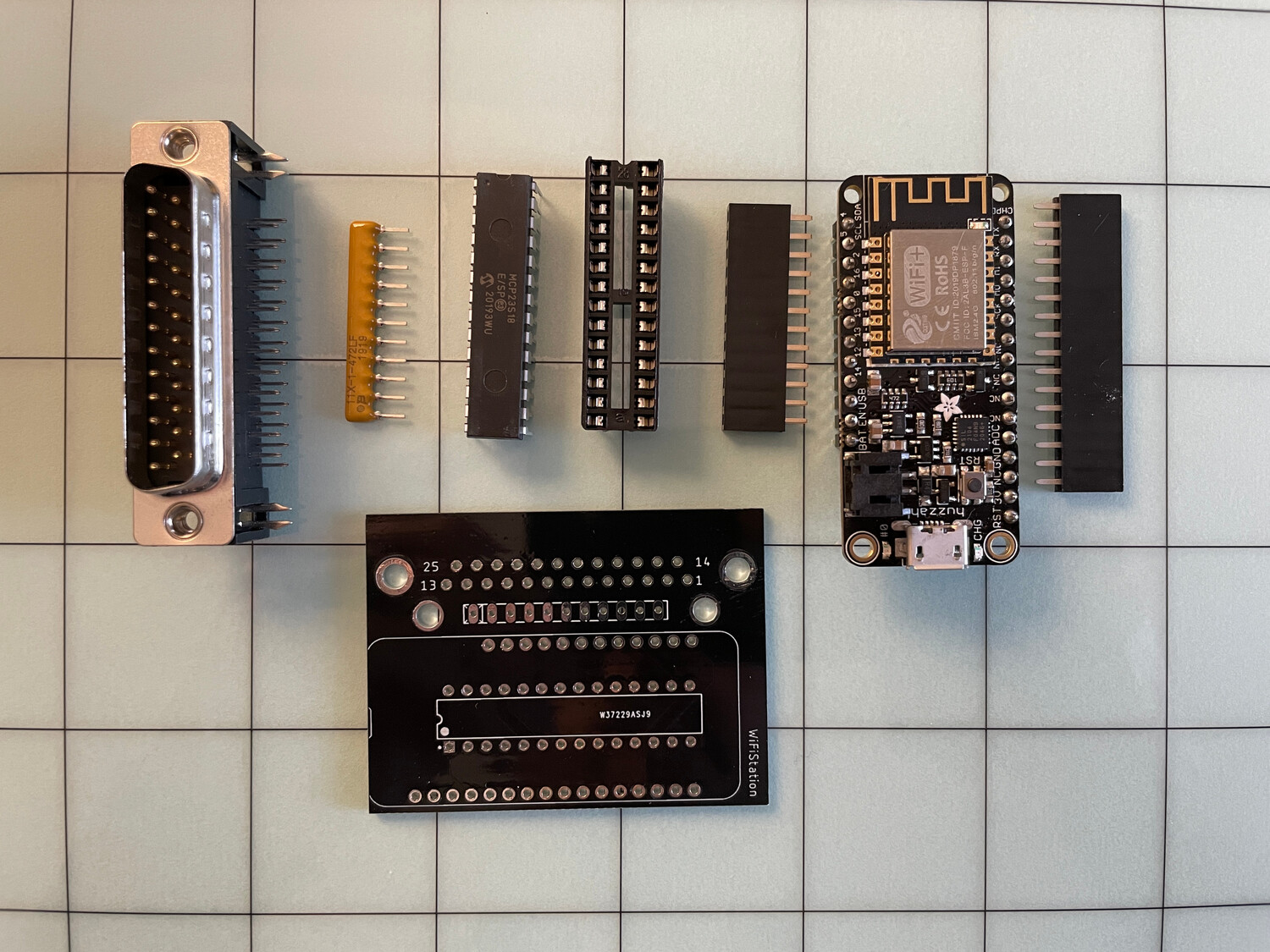
You should have received all of the following parts:
- DB25 90-degree connector
- 4611X-101-472LF 4.7k Ohm bussed 10-resistor array
- MCP23S18 SPI chip
- Socket for MCP23S18 chip
- 12-pin header and 16-pin header
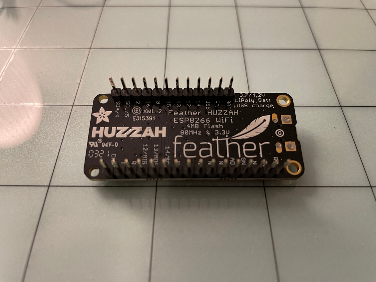
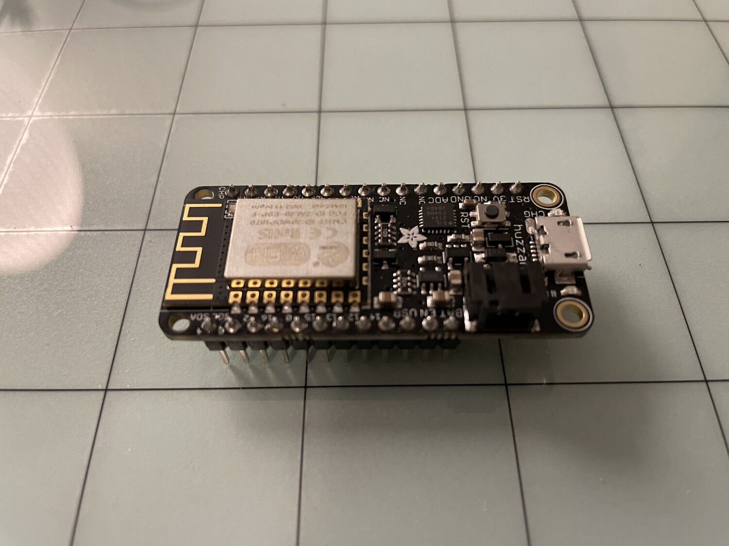
- Adafruit Feather Huzzah ESP8266 module with pin headers (your pin headers may already be soldered to the Huzzah module)
- WiFiStation PCB
Step 2: Solder Resistor Array
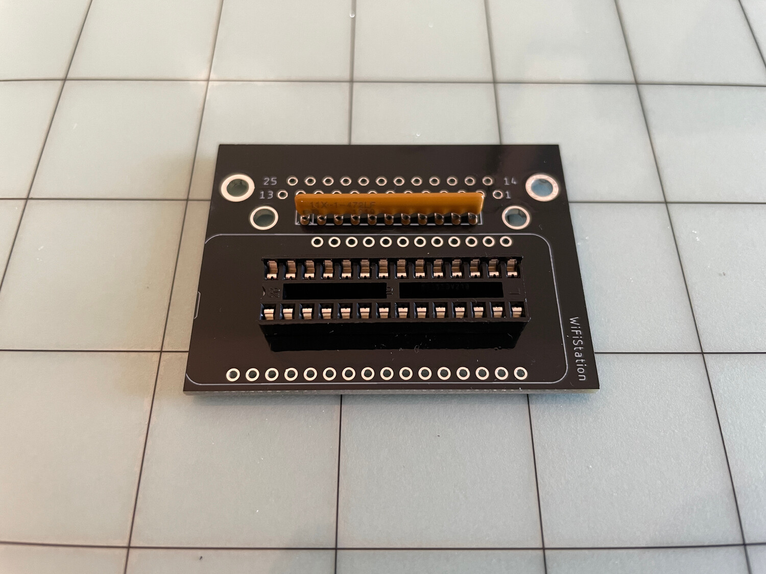
Verify the positioning of the resistor array. With the WiFiStation board facing as shown, the resistor array should be soldered with its pin 1 (the one with a gray dot over it) onto the board where the "X" is on the left-most position. The writing on the resistor array must be facing you.
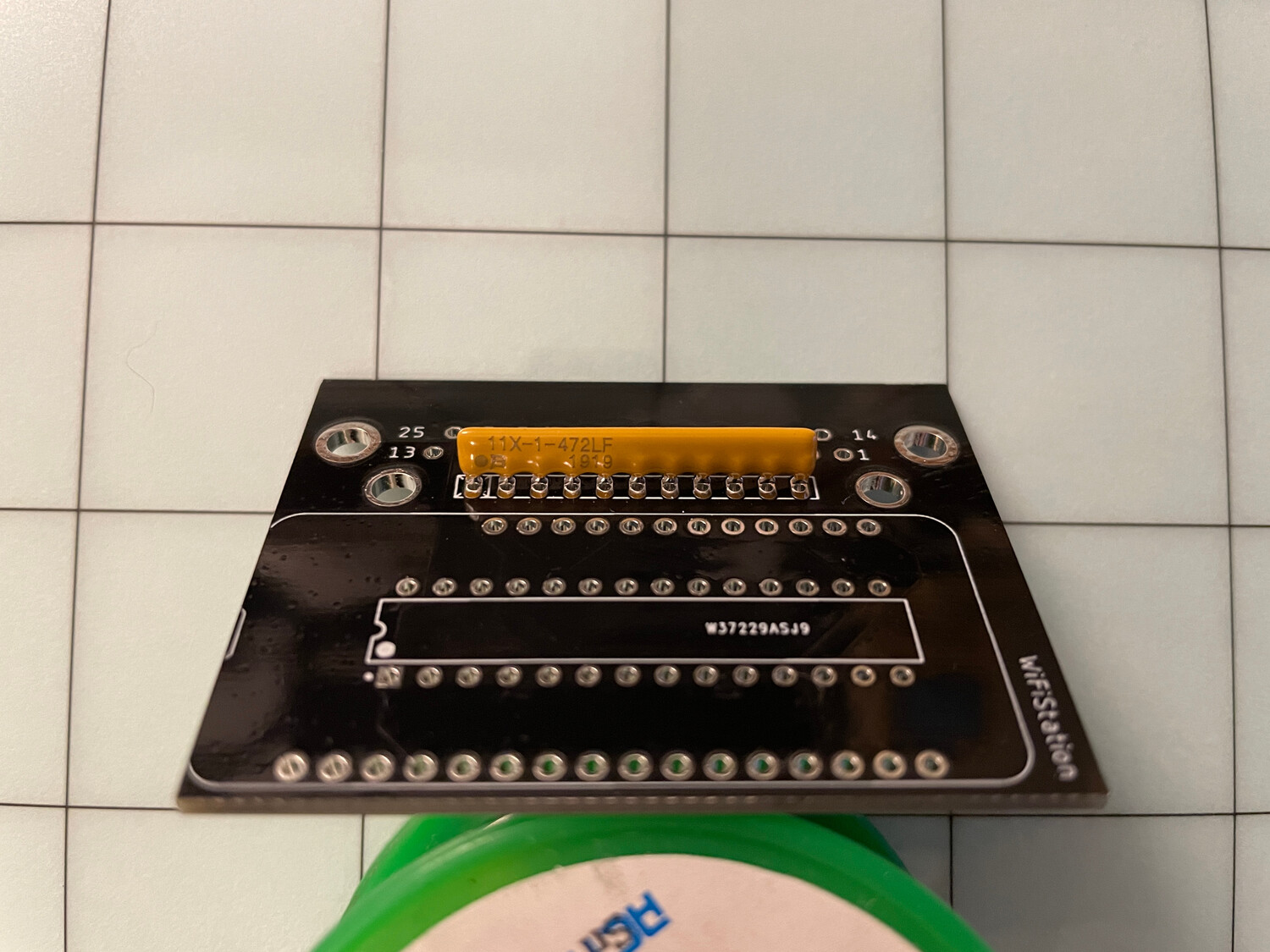
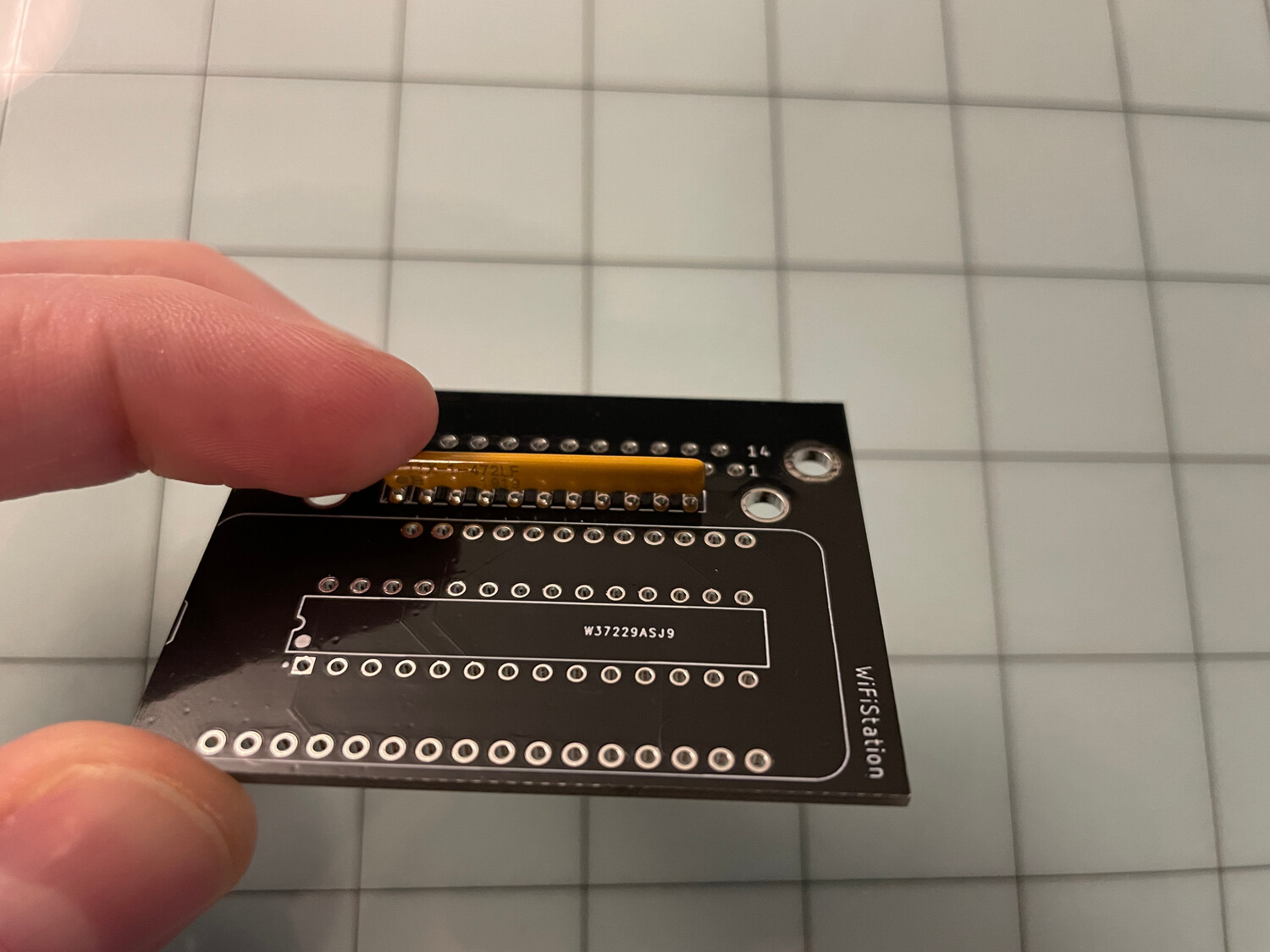
If you don't have a "helping hands" stand to hold parts for you, it may be kind of tricky to hold the resistor array in place while also soldering it. I've found that it's helpful to add a bunch of solder to your soldering tip, hold the array with your index finger, flip the board over, and then glob the solder onto one of the resistor pins while still holding the array with the other hand. This should provide just enough hold to allow you to free your hand, so you can start properly soldering at the other end of the array.
If you try to solder the array with the board lying down without first securing a pin, it will be very crooked.
Step 3: MCP23S18 Socket
The chip socket has a small indentation on one side, which should line up with the indentation printed on the board.
I recommend doing the same technique as the resistor array and holding it with one hand, globbing a bit of solder onto one pin to get it to stick, and then starting to properly solder it starting at its other end.
Step 4: Pin Headers
This picture shows the DB25 connector already soldered, but I recommend doing the pin headers first. Without the DB25 connector installed, you should be able to insert each header, flip the board over onto a hard, flat surface, and then solder the headers into place with them properly sticking straight upward. If they are soldered on even slightly crooked, you'll have a hard time inserting the Huzzah module pins.
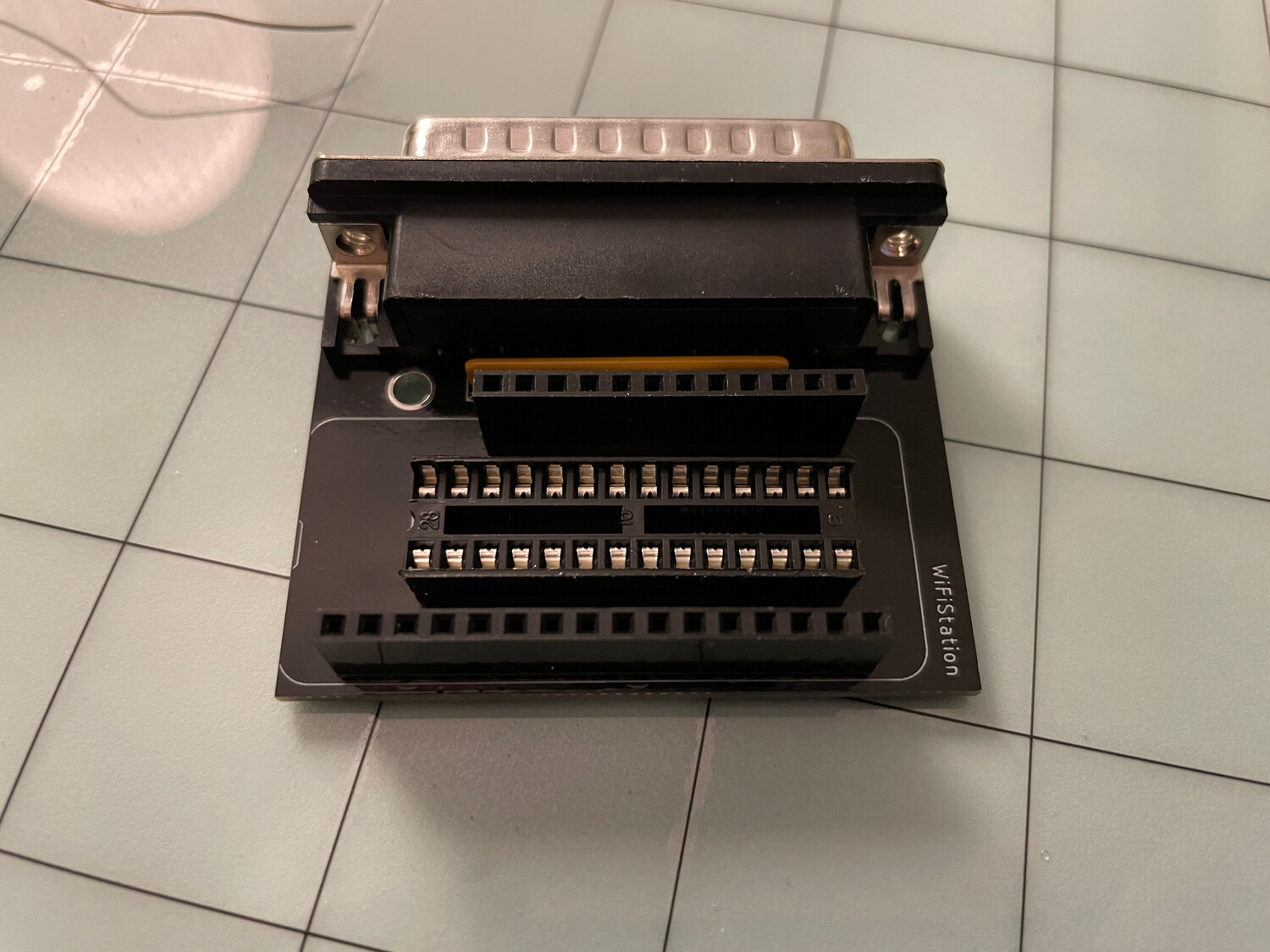
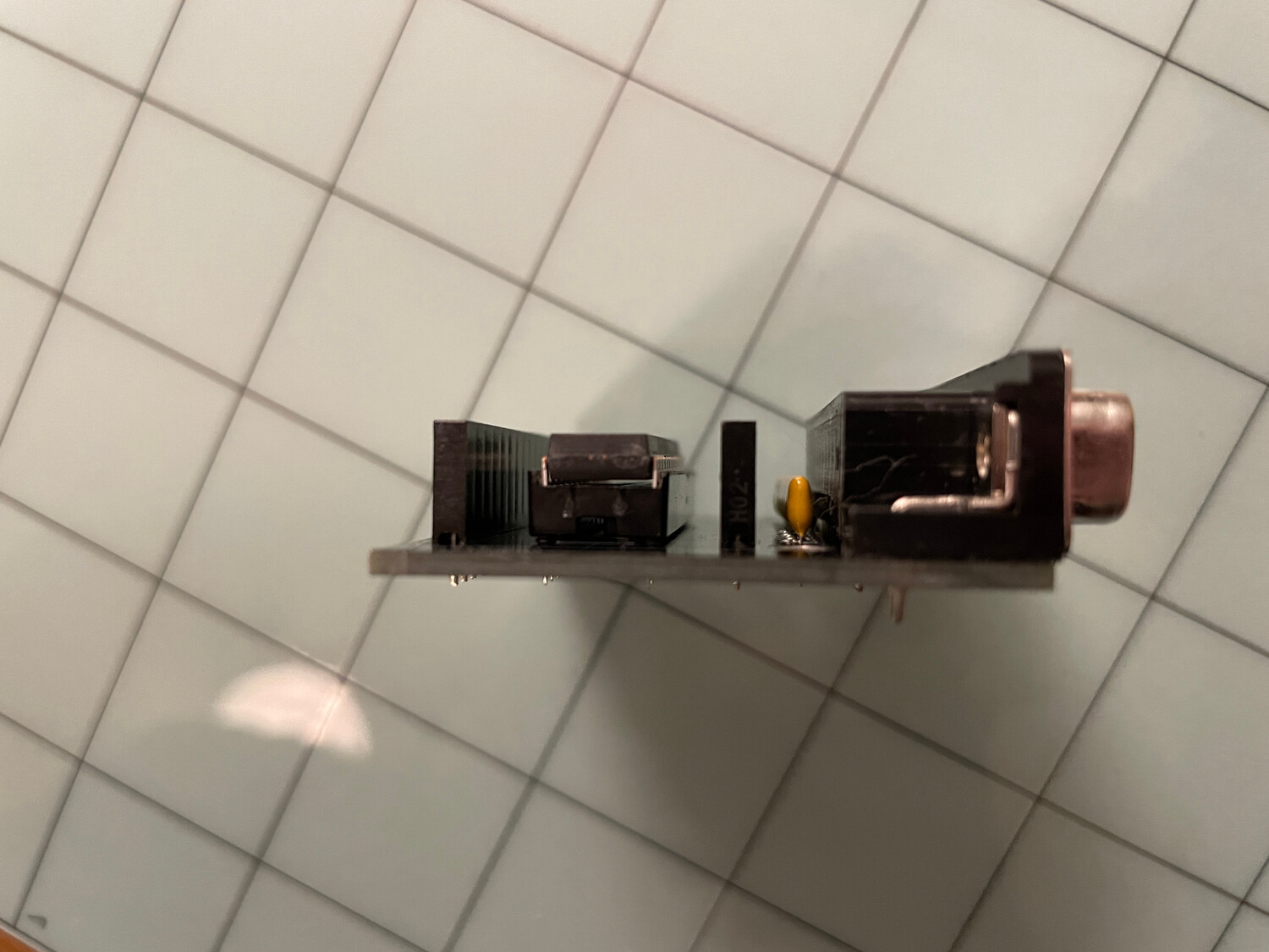
Step 5: DB25 Connector
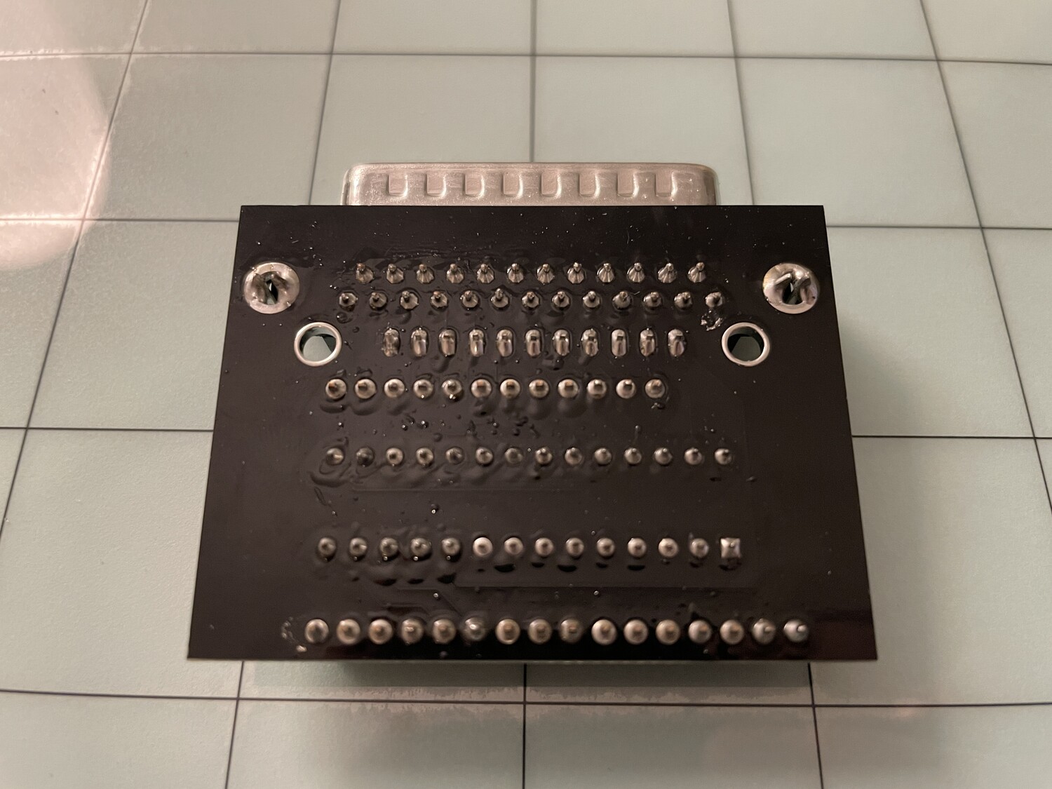
Now install the DB25 connector, making sure all of the bottom pins are straight. Add some solder on the retaining clips, but you don't have to fill the entire holes.
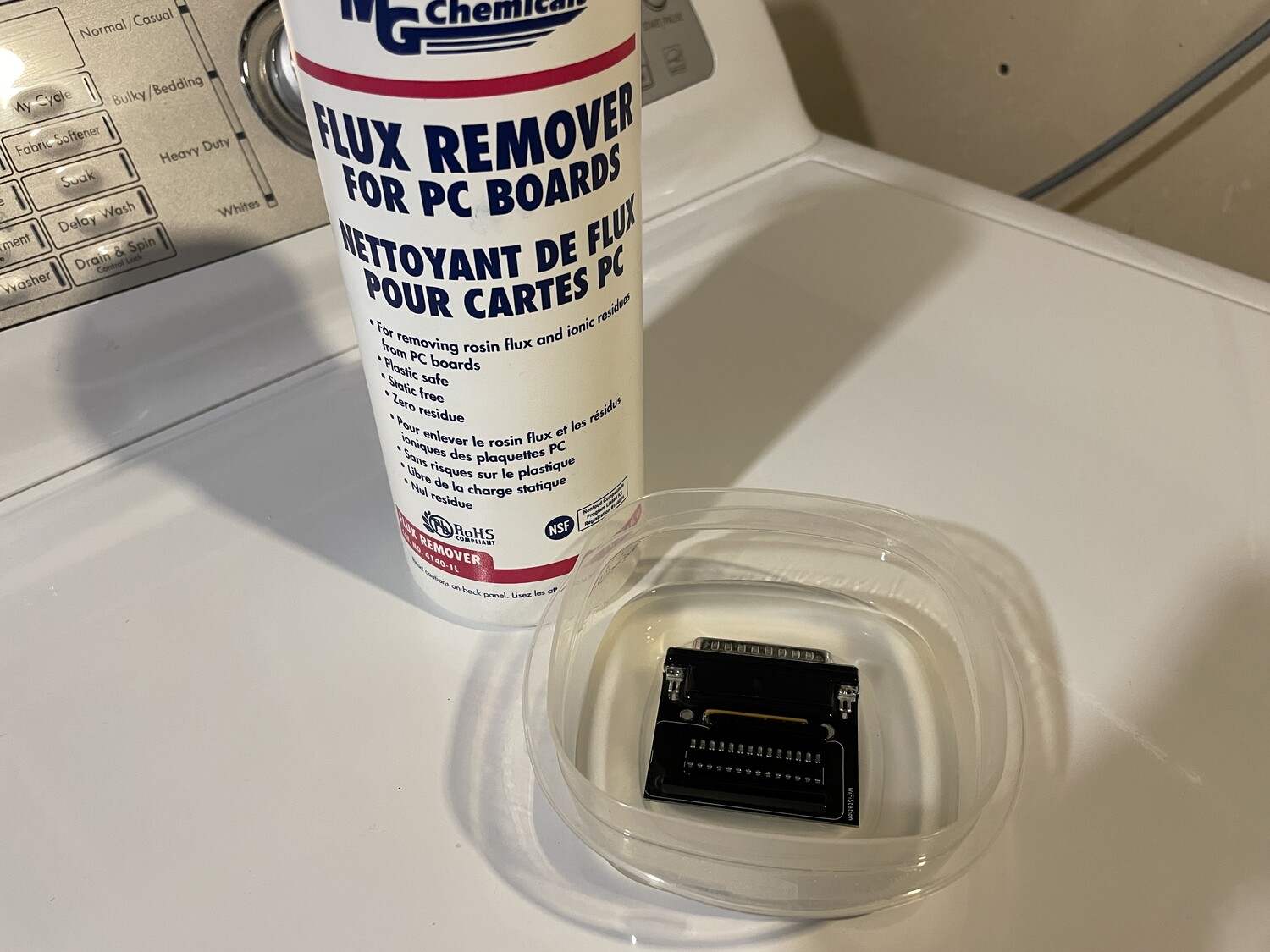
Step 6: Clean the Board (Optional)
If you have it, I recommend giving the board a bath and light brushing in some flux remover. You've done a lot of soldering in a small area and you may have a large amount of flux buildup on the board.
Step 7: Install the MCP23S18
With all of the soldering on the board done, install the MCP23S18 while verifying that its indentation matches up with the indentation on the socket. With the board facing you like this, the writing on the chip should be upright.
You will probably need to bend the pins slightly, as they come wider than the socket. I recommend laying one side of pins on a flat surface and very carefully rolling the chip over to bend one side of pins at a time, rather than trying to individually bend each pin.
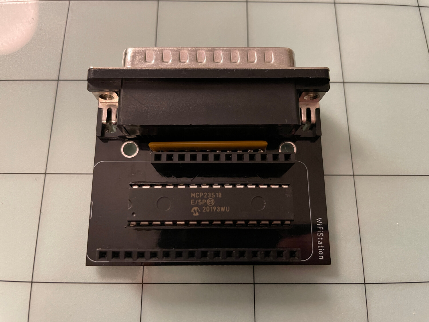
Verify that all of the pins made it into the socket correctly.
Step 8: Solder Huzzah Module Pins
Depending on which Huzzah ESP8266 module you received, the pins may already be soldered on from Adafruit, or you will have to solder them on yourself.
There will be two rows of pins, one with 12 pins and one with 16 (or two of 16, just break off 4 from one).
Step 9: Install the Huzzah ESP8266 Module
Insert the Huzzah ESP8266 module pins into the headers and you're all done! You can now proceed to the other steps of the Getting Started guide.
