Adding a USB Port to the ThinkPad X1 Nano (the Hard Way)
I wanted to add an internal USB port to my ThinkPad X1 Nano which should have been a fairly easy thing to do, but it wasn't.
Of course, if I were still using my Framework Laptop it would be as easy as plugging in a custom module but I've been using my X1 Nano as my primary laptop for quite some time now.
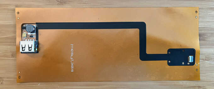
Table of Contents
Logitech Mouse
As convenient as the TrackPoint is on my ThinkPad, having a mouse with a scroll wheel and 4 buttons is very handy. I use a Logitech mouse which can connect wirelessly to a USB dongle over RF, providing lower latency and better battery life than Bluetooth. The mouse also supports Bluetooth but OpenBSD doesn't, so USB dongle it is. This might seem annoying on a laptop with only 2 USB ports, but it's usually plugged into a USB-C dock under my desk which also routes power to the laptop so everything rides over a single USB-C cable and I don't even notice the dongle.
That is, until I unplug my laptop and this supposedly wireless mouse loses its connection and I need to remember to bring the dongle along with a USB-A-to-USB-C adapter. Yuck.
I also have the same problem when using my AirPods with the laptop. Since OpenBSD can't connect to them natively over Bluetooth, I use a Creative BT-W3 to handle Bluetooth which then presents a USB audio interface to OpenBSD. (Unfortunately I can't leave that connected all the time because as soon as I switch the AirPods to connect to my phone, the BT-W3 will take over the connection within about 10 seconds if I'm within range of my laptop.)
Clearly my life would be easier if OpenBSD had a Bluetooth stack again, but it's a lot of work and I don't want to write it. Perhaps it's easier to hide a USB port inside of the laptop where at least the mouse dongle can hide out.
M.2
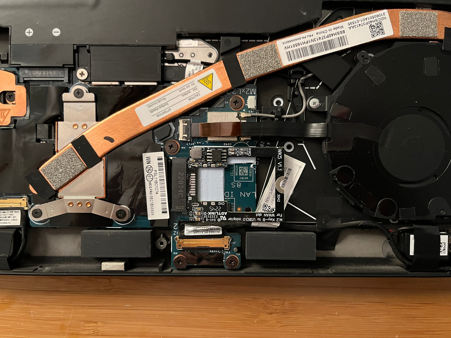
The X1 Nano has an available M.2 (B-Key) slot for adding an optional WWAN card. On many other laptops, it would be straightforward to buy an M.2 USB card, install it in this slot, and instantly gain an internal USB port (or two).
Fun fact: in addition to providing a PCIe interface, M.2 slots also have pins
for providing a USB connection.
Many Wi-Fi cards that also provide a Bluetooth device use both of these sets of
pins to present the Wi-Fi interface over PCI and Bluetooth over USB.
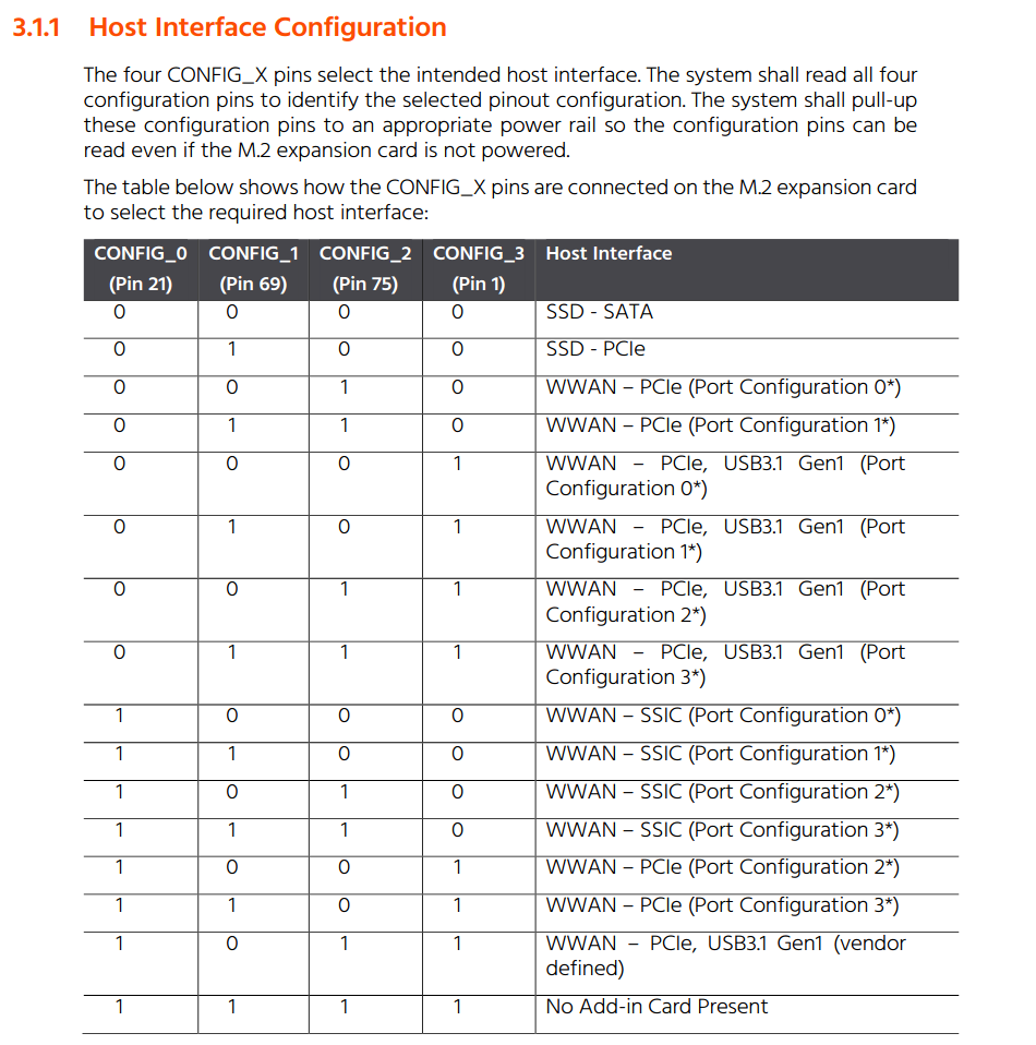
There are a set of
4 configuration pins
that the card uses to tell the host what type of interfaces are being used.
M.2 USB cards don't even have to provide their own USB controller, they just
need to connect the M.2 USB pins to a USB port, shift 3.3V to 5V needed for USB,
and ground certain configuration pins.
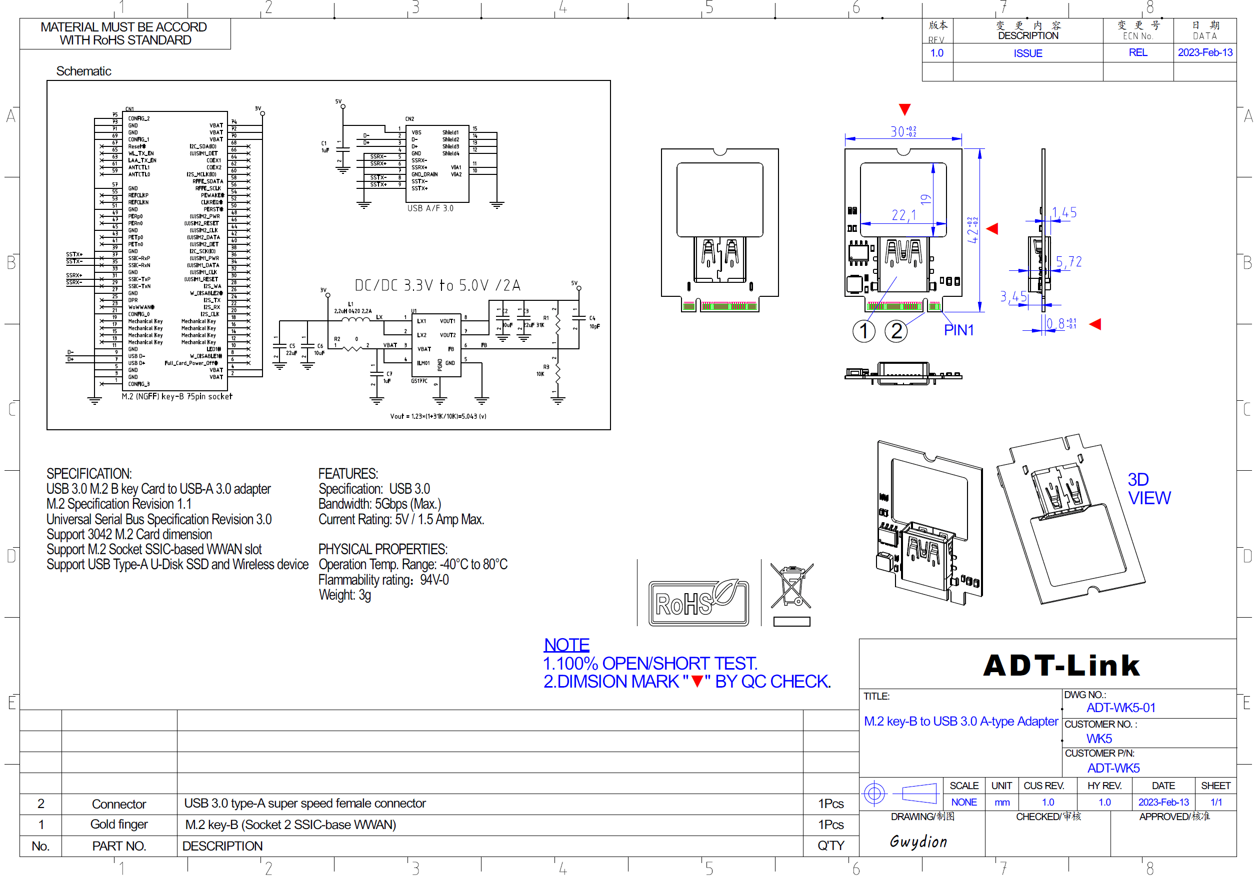
The
schematic
for such a card shows how only the USB SSIC, CONFIG, VBAT, and GND pins
are wired up.
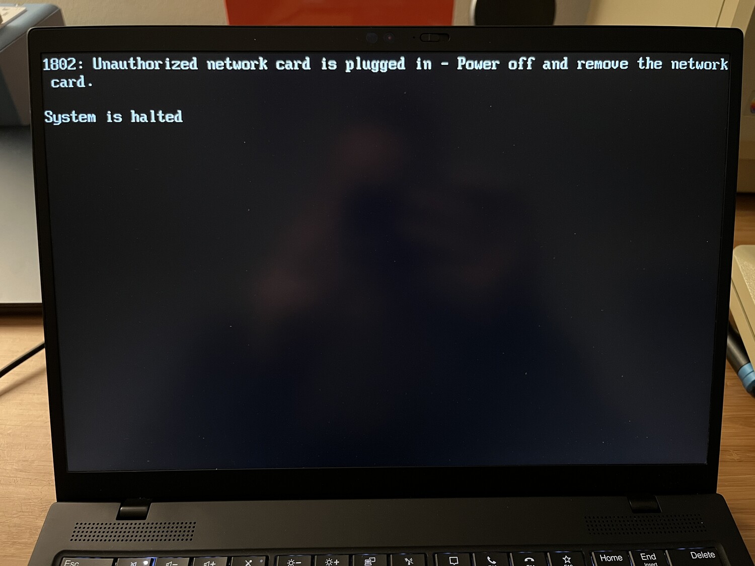
Unfortunately, Lenovo continues to implement a stupid network card whitelist that IBM started over 20 years ago on its ThinkPad models. If the card in the M.2 slot is not advertising a known PCI vendor and product ID in the whitelist contained in the BIOS (now UEFI firmware), the ThinkPad will refuse to boot:
I briefly considering making a custom M.2 PCI card that forwarded the USB pins but also added some kind of microcontroller that pretended to be a known good WWAN card, at least as far as its vendor and product ID. I also thought about a card that used some kind of timer chip to keep the configuration pins disconnected long enough to let the machine boot while thinking nothing is in the slot, and then connect them to the USB port. These both seemed difficult to implement, so I started down a different route.
Firmware Hacking?
To investigate the whitelist, I first needed a valid WWAN card to know what
vendor and product ID to look for.
This took a bit of trial and error but I eventually found the
Qualcomm X55
card to work, which has a vendor of 105b (Foxconn) and a product of e0ab.
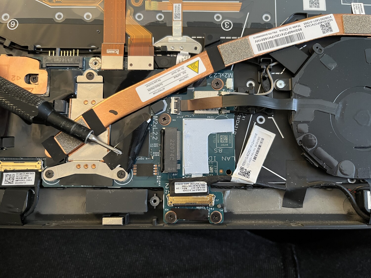
Next, I needed to look at the actual firmware code to see how its whitelist worked. After poking around the motherboard, I located the firmware flash chip right next to the M.2 slot under a plastic sheet, and it's a Winbond W25R256JV 32 Megabyte 8mm x 6mm chip.
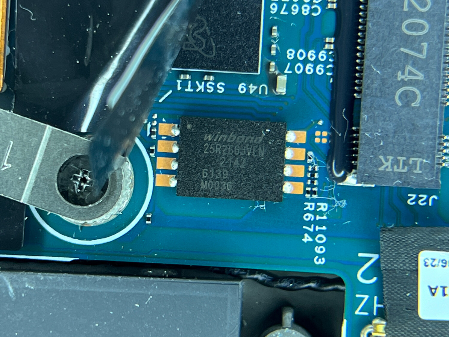
Since this flash chip has such a low profile, my usual SOIC chip clips couldn't grab onto it. I didn't want to desolder it and risk damaging it, so I purchased a pogopin probe that worked well, though it's a bit tiresome to use because it requires a steady hand applying downward pressure for about eight minutes for a full read and write.
Using the probe with my
CH341A reader
and
AsProgrammer
on a Windows laptop (ironically, my Framework laptop), I was able to read the
firmware image and look for 5B 10 AB E0 (the vendor and product in
little-endian format).
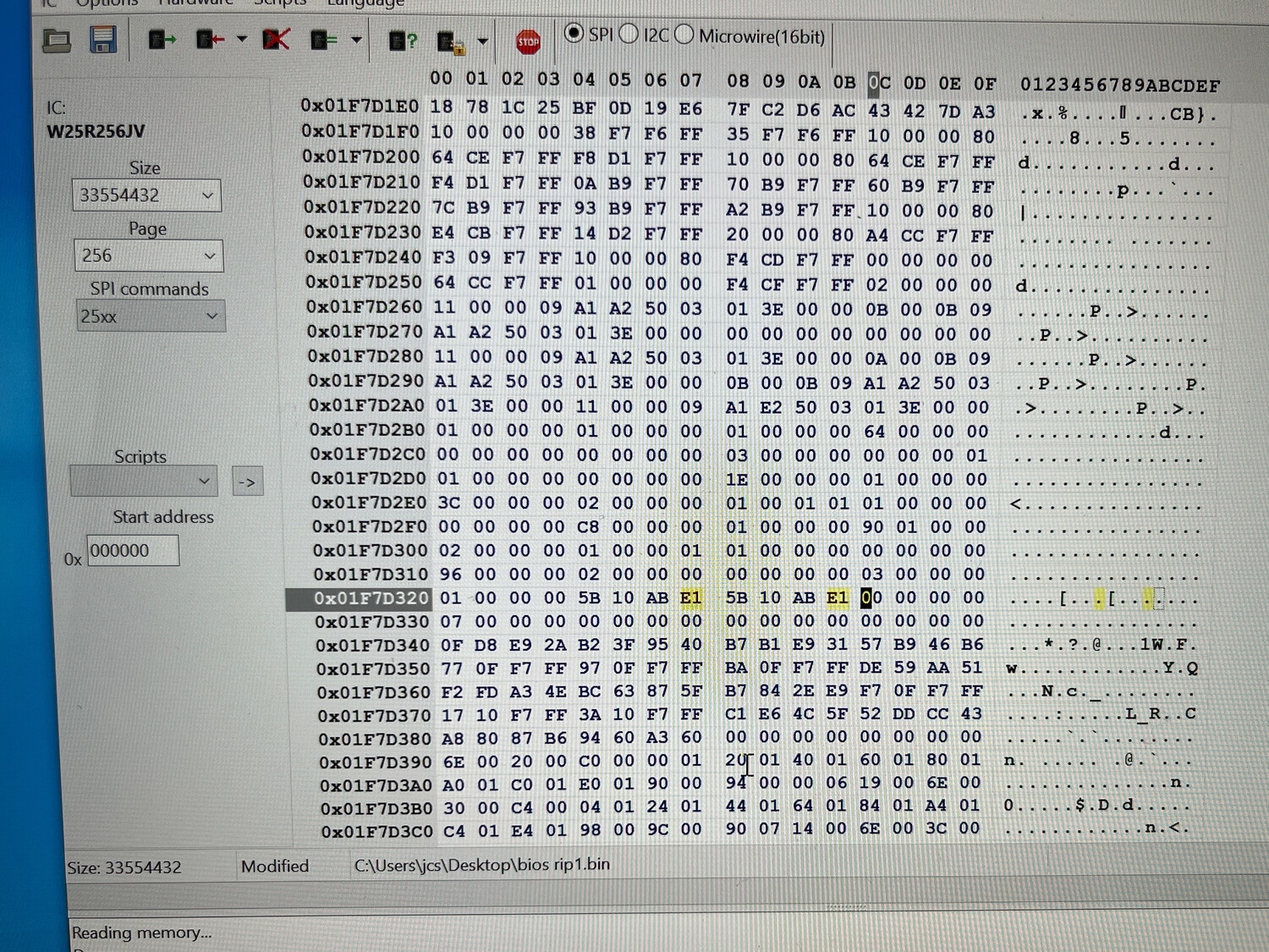
I changed E0 to E1 in both instances, hoping it would then boot with an
unauthorized card error, indicating I had found the proper whitelist.
Unfortunately this caused the machine to boot with this error:
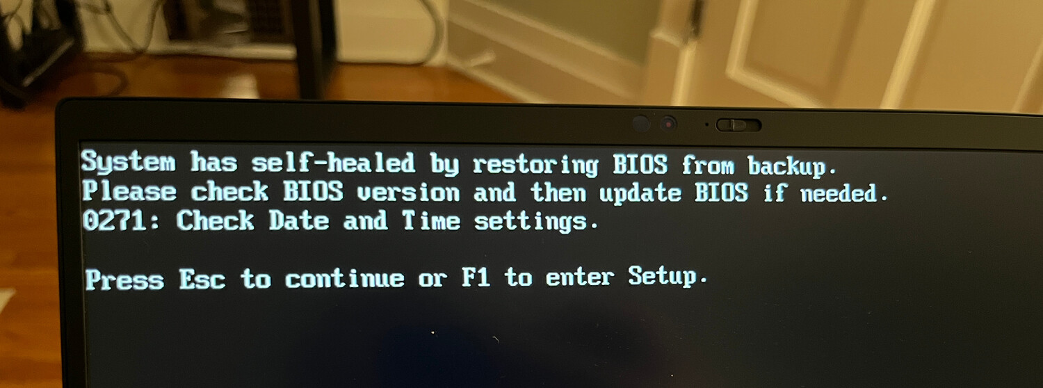
Apparently Lenovo uses a thing called Secure Flash Authentication which calculates a checksum of the firmware image and validates it against a signed value and if it fails, the firmware is overwritten with a known good version. I'm not entirely sure how this works, though. Where is the known good copy stored? Another 32MB flash chip? What is doing the flash verification? It can't be the firmware on the flash chip itself because that could be toast and it will still self-heal. Is the verification code running from the known good flash? Does it do this verification on every boot, reading the entire 32MB before POSTing?
After wasting a week or two on this and playing around with some very sketchy Windows software for modifying UEFI payloads, I gave up going this route.
Fingerprint Reader
While staring at the motherboard with the battery removed, I remembered that the fingerprint reader that sits next to the touchpad connects over USB, though I usually have it disabled in the firmware. I wondered if it would be possible to use whatever connection that board uses to connect an arbitrary USB device.
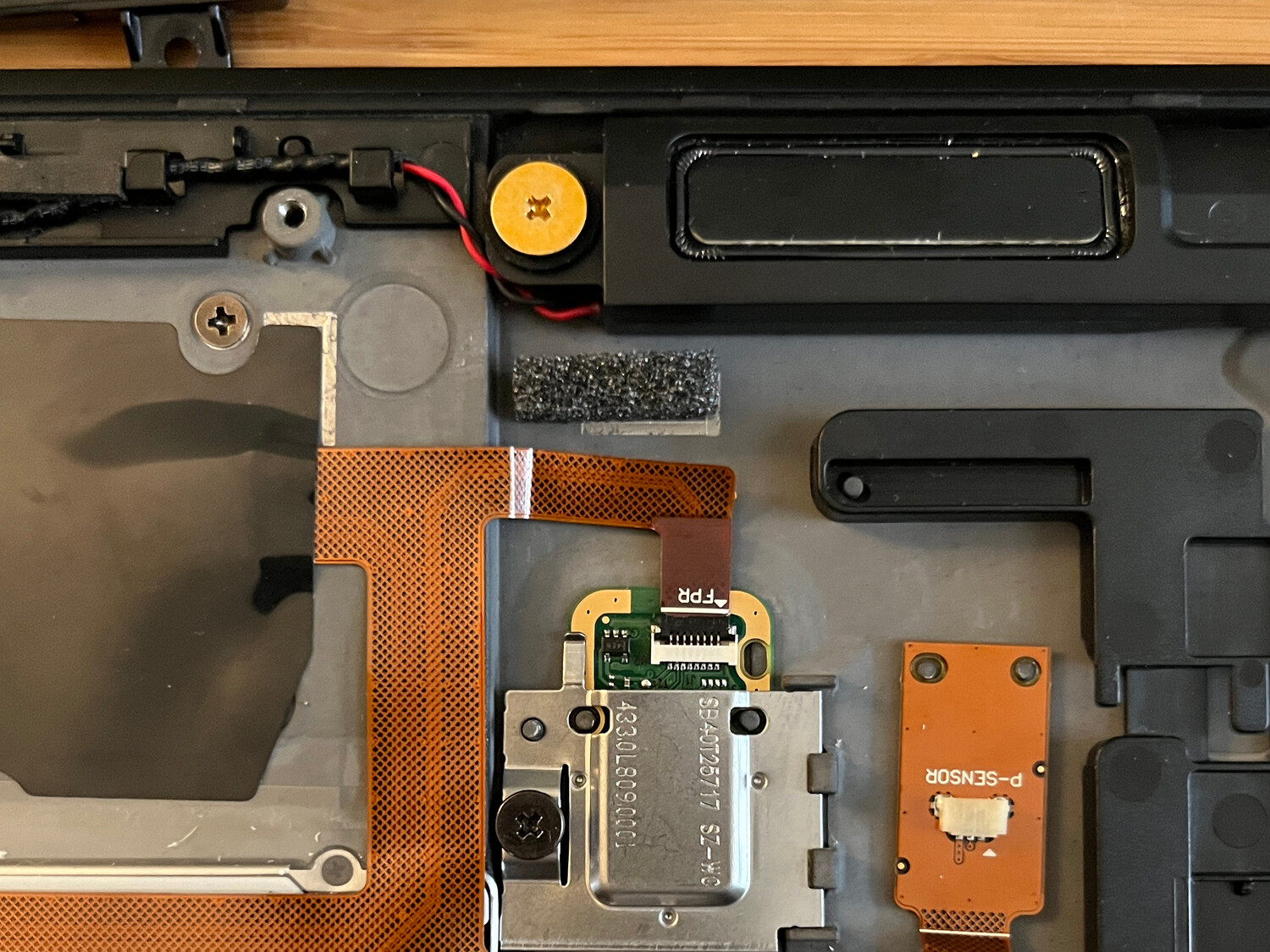
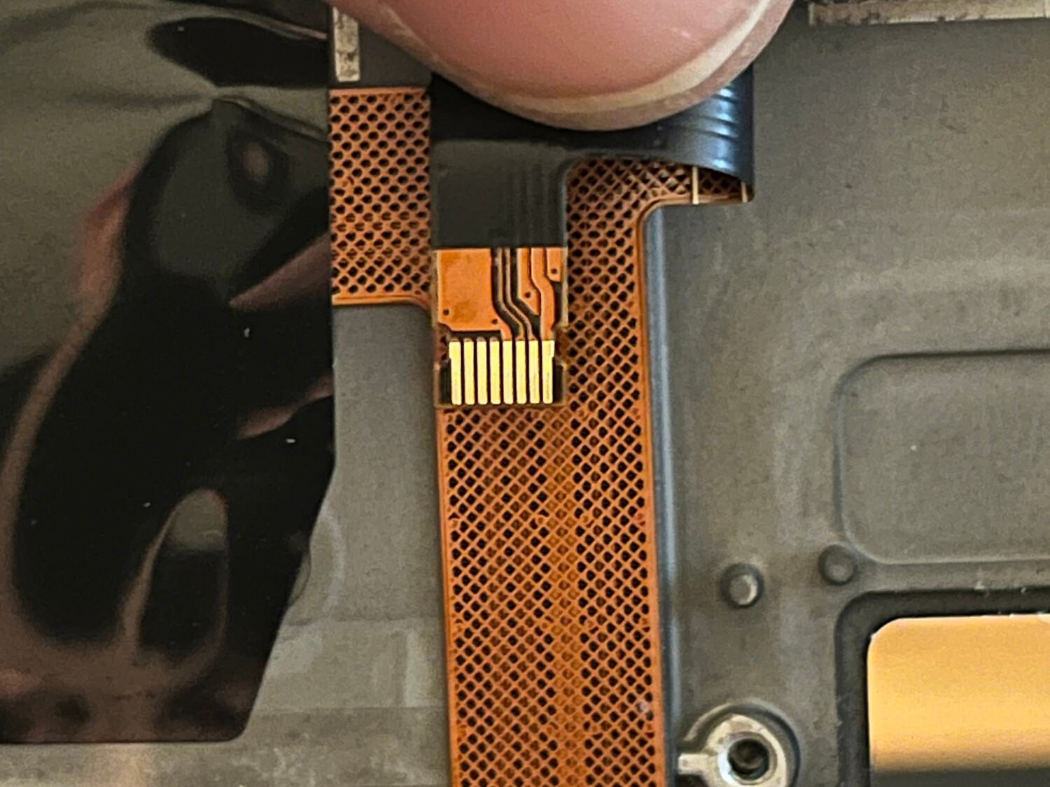
The fingerprint reader board used an
FFC
8-pin connector but only 4 of its pins were connected which is also the amount
needed for a basic USB 2.0 connection.
I bought an
FFC 8-pin 0.5mm breakout board
and determined pin 1 to be USB VCC, pin 2 DATA-, pin 3 DATA+, and pin 4
GND.
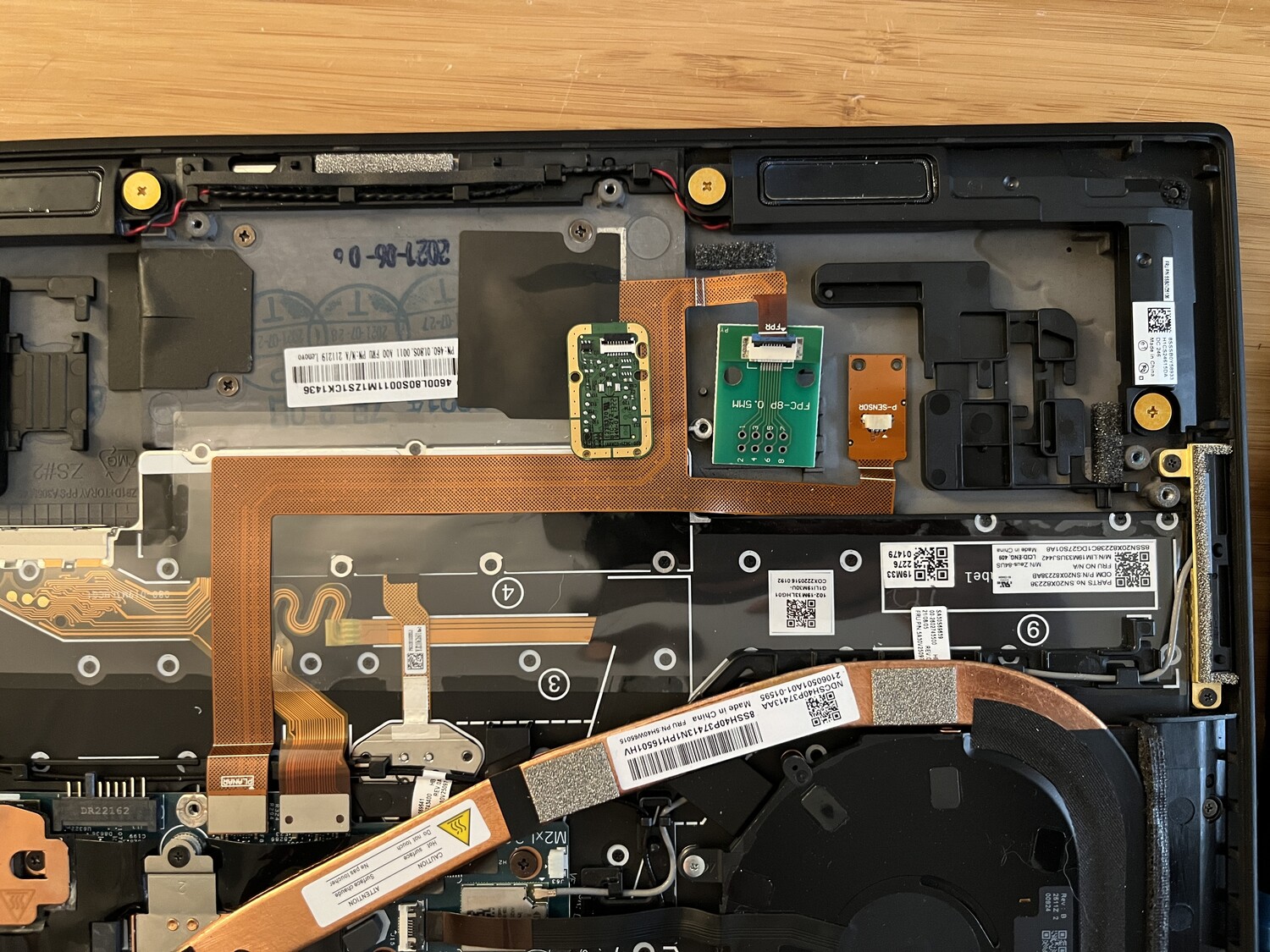
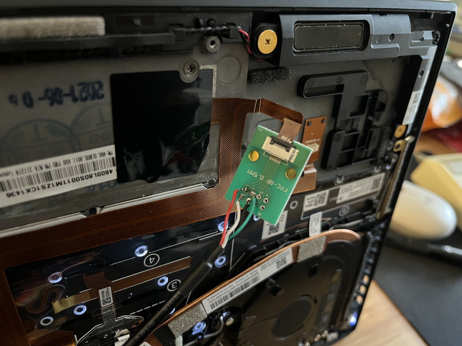
Conveniently, there are two rubber/foam blocks adhered to the case on both sides of the display connector. By removing one of them, there is just enough space to house a USB connector in a permanent location:
So my (eventual) idea was to create a new flex PCB that goes in place of the fingerprint reader and has an FFC 8-pin connector for the motherboard cable, then routes the four USB pins down to a USB port next to the display connector. While normally a USB port wouldn't hold up well on a flexible PCB, this one is going to house a USB device that is semi-permanently installed, so it won't undergo the stress of constant removal and insertion.
With the temporary USB port soldered up, I crossed my fingers and powered on the machine, and nothing started on fire. Once OpenBSD booted, I plugged in some USB 2.0 devices and most of them attached… except the one device I actually needed: the Logitech Bolt receiver. There were no port errors, it was just never detected as if it weren't powered up.
USB Power
After checking again with a multimeter, I realized that the FFC cable going to the fingerprint reader is only carrying 3.3V instead of the usual 5V for USB. Apparently the fingerprint reader is designed to only need 3.3V for its USB connection (possibly taking power from nearby i2c components which use 3.3V), and most of the USB devices that I tried worked with only 3.3V as well. Since the Logitech Bolt required more than 3.3V, I needed to boost the voltage to 5V.
While doing some research, I came across these boost boards which use an ME2108 to boost <5V to 5V. I bought some and wired one up inline with the external USB port and it did provide the necessary 5V to make the Logitech Bolt adapter work, so I just needed to incorporate that circuit into my flex PCB.
Designing a PCB
After whining about having to do PCB design and dreading using EAGLE again, I found EasyEDA which offers a free in-browser PCB design platform (which worked in Firefox on OpenBSD) that ties in with JLCPCB for PCB printing and assembly.
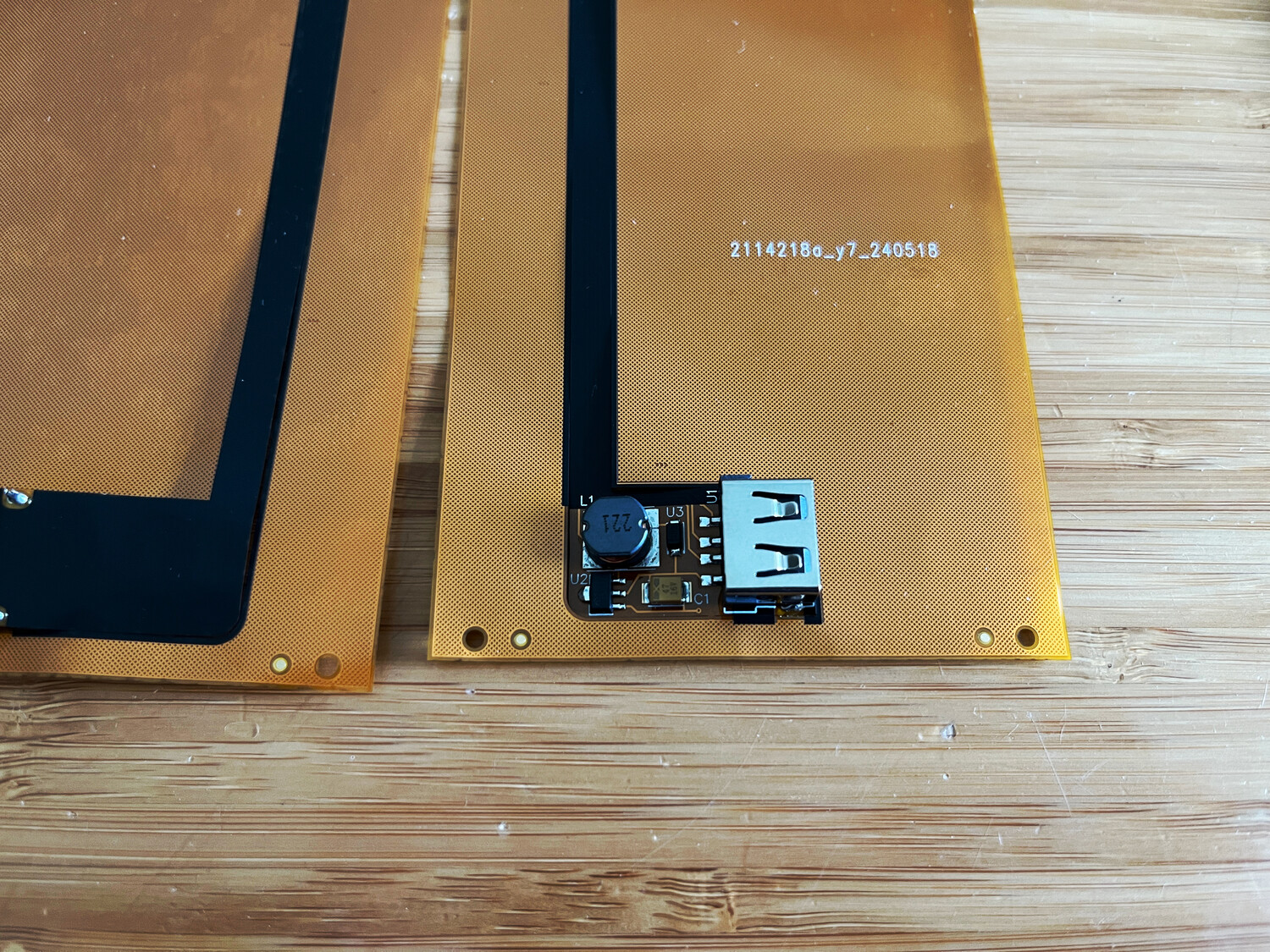
I got out my calipers and took a bunch of measurements of the fingerprint reader board including its various oval-shaped holes, then designed a similar board in EasyEDA. I desoldered the components on one of the boost boards and figured out how they each connected, and incorporated those onto my PCB.
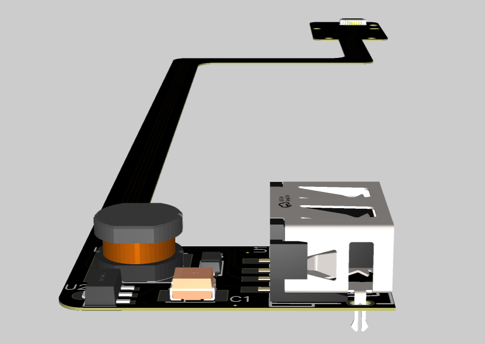
I also opted for JLCPCB's PCB assembly service so they would deliver completed boards with the FFC connector and USB port components included and soldered on. This would save me from having to source them separately and deal with SMD soldering.
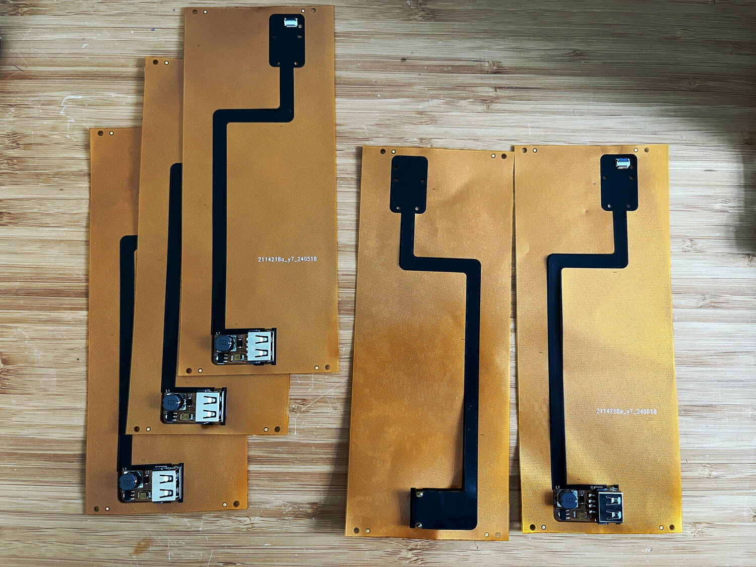
A few weeks later, I had my printed flex boards all assembled and just needed to punch them out of their perforated sheets and trim the legs on the USB port. The black coating over the flex board is for EMI shielding.
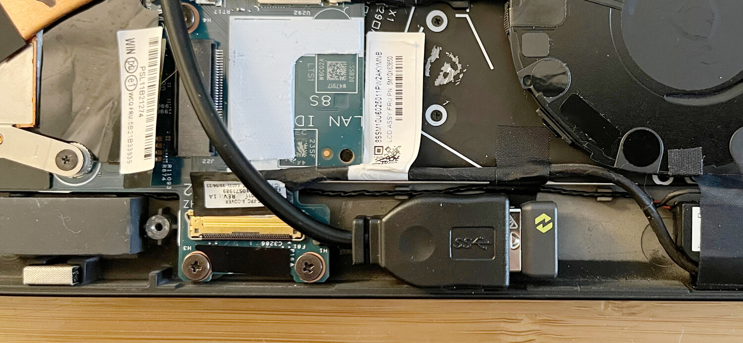
The top part of the PCB replaces the fingerprint module underneath its metal cage:
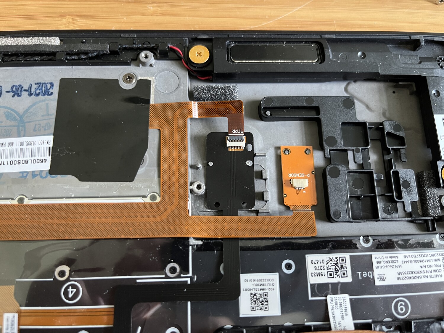
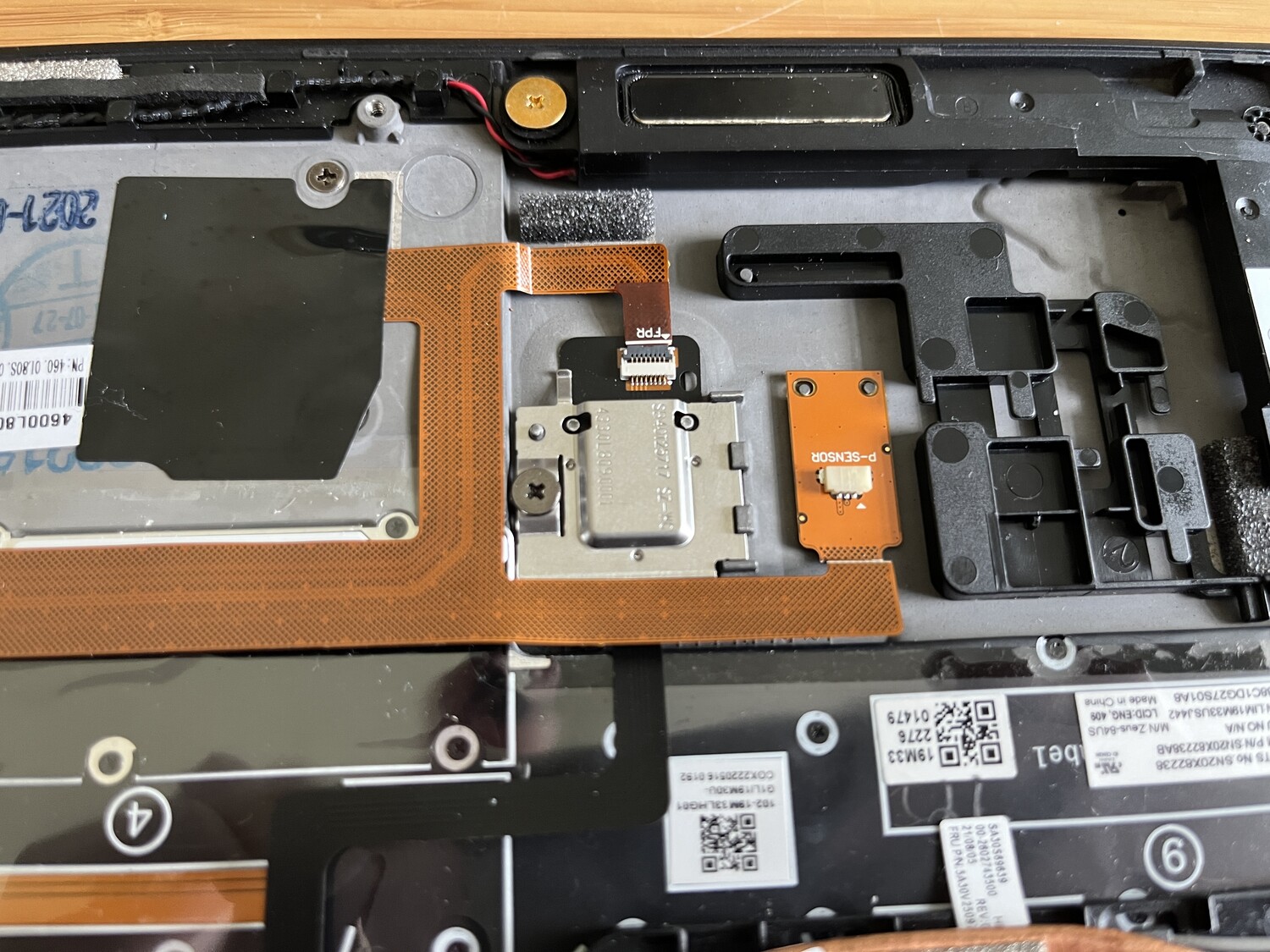
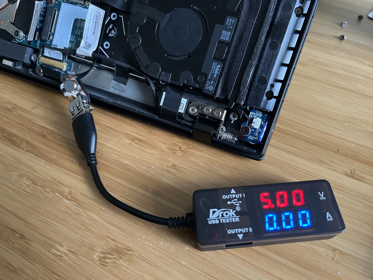
It then snakes under some other cables, the battery, the heatpipe, and under the display cable to finally put a USB port where I need it, and a USB multimeter confirms that the power is correctly boosted to a solid 5V:

That screw hole standoff on the bottom cover shown there near the USB port did need to be sanded off to clear the height of the USB device. This standoff normally has a plastic clip screwed into it that clips under the case and isn't one of the load-bearing screws that goes all the way through the bottom cover.
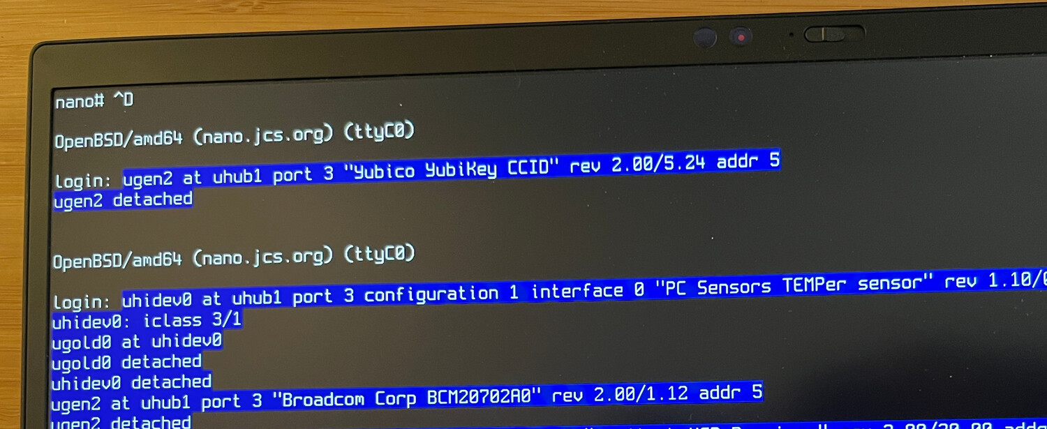
And now with nothing external plugged in, my Logitech Bolt adapter is attached to the root USB hub and my wireless mouse is again wireless:
nano:~$ usbdevs -v
Controller /dev/usb0:
addr 01: 8086:0000 Intel, xHCI root hub
	 super speed, self powered, config 1, rev 1.00
	 driver: uhub0
Controller /dev/usb1:
addr 01: 8086:0000 Intel, xHCI root hub
	 super speed, self powered, config 1, rev 1.00
	 driver: uhub1
addr 02: 046d:c548 Logitech, USB Receiver
	 full speed, power 98 mA, config 1, rev 5.00
	 driver: uhidev0
	 driver: uhidev1
	 driver: uhidev2
addr 03: 13d3:5411 Azurewave, Integrated Camera
	 high speed, power 500 mA, config 1, rev 61.01, iSerial 0000
	 driver: uvideo0
	 driver: uvideo1
	 driver: ugen0
addr 04: 8087:0026 Intel, Bluetooth
	 full speed, self powered, config 1, rev 0.02
	 driver: ugen1
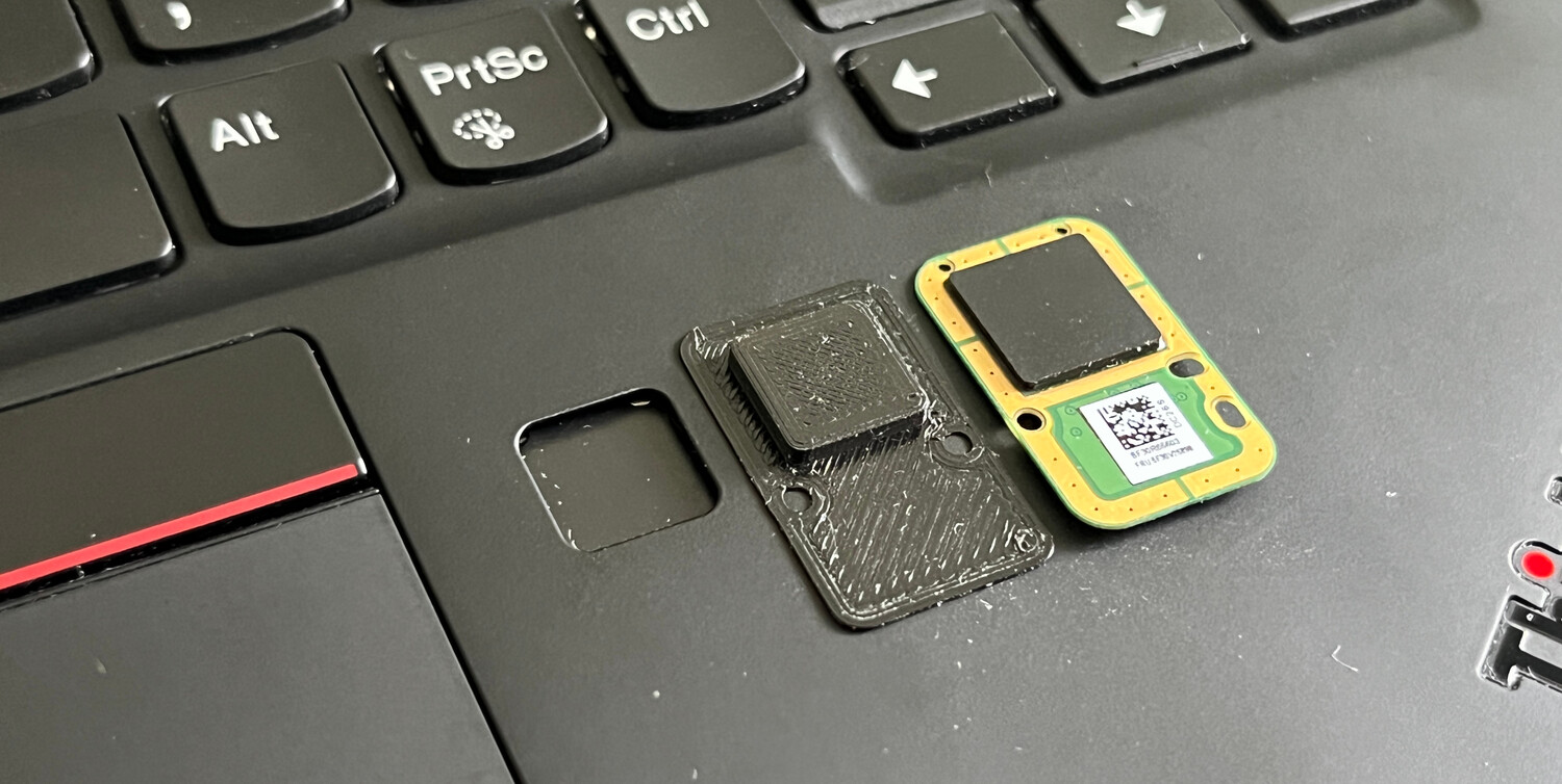
3D-Printed Shim
Since the original fingerprint reader had a raised pad and the flex PCB is just flat, there's a slight depression in the keyboard deck where the fingerprint reader used to be. I designed a 3d model to sandwich between the PCB and the keyboard deck that will make it more flush, but I still haven't perfected it. This may just require some matte filament and acetone smoothing to eliminate the 3d printing lines.
On a side note, I thought it would be neat to house a Yubikey in this hole instead or maybe a super tiny LCD.
Update: I eventually printed a filler out of flexible TPU.